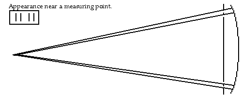
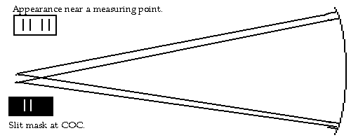
The original drawing from John Sherman is below. It shows a mask at the mirror but other writings from H. E. Dall (the originator of the DALL null test) tend to indicate that the mask is actually at the COC.
      mirror              |_____________________|
      mask                -- - ------------- - --
                              \             /
                               \           /
                                \         /
                                 \       /
                                  \     /
                                   \   /
                                  +----+     _________
      beamsplitter                | \  |    |________| 5 mW laser|
                                  |  \ |    |________|
                                  +----+
                                   +-+
      microscope                   | |
                                   | |
                                   +-+
To the right are two versions of how the test can be done. The upper is two holes in a mask that will produce a single spot at the COC and pairs of lines off of the COC. I'm not too sure which way is the better way, 4 lines equally spaced or 3 lines with one of each side overlapping. |
 |
 |
The beamsplitter & microscope are on an x-y stage I made originally for the caustic test. I tried a laser pointer on the stage, but it wasn't bright enough, so I just push the laser until the beam hits the fiber (what fiber? A beam spreader GRIN LENS? - Bob May), which is perpendicular (?) and spreads the beam out into a line across the mask. (maybe this is the use of the diameter of a clear fiber to do a beamspreading function which is rather inefficient). I measure the distance from mirror vertex to the point where the returns from the two hole pairs merge (once with a tape measure, the rest by increments measured by micrometer head). I don't think the (classic Gavriola) caustic test is accurate enough for RC casses, so I made this rig.
-- Jim Burrows -- burrjaw at earthlink.net
Be aware that my test might be different than the "double slit test".
The tester has been disassembled for quite a while, the mirror is coated and installed in an OTA. The mask holes were 5 mm wide; with just one hole open on each side, the images were quite wide and hard to match. When I opened a pair of holes, each image had a bright narrow central band with two dim side bands. (Diffraction of the holes producing a bright section?) Usually it was easy to match the hole-pair images, but occasionally there was some ambiguity about which was the central fringe. What I did was to measure each zone twice, once with hole pairs, once with a single hole, then average if they were close, take a look again if they differed by too much.
Lateral measurements such as in caustic tests are intrinsically less accurate than the longitudinal measurements in good ol' Foucault, which is why it's standard procedure to write down the lateral measurements with another digit.
Yup, there're two ways. The test I mentioned has the double slit light source, as I understand the description. That is Dall's test. He has a mask with holes on the mirror.
There is also the test (or, maybe more than one test) where the slits are in the mask on the mirror, and more than one slit is used at a time. Vaisala did this test, which Nils Olof recently mentioned. http://www.kushnir.newmail.ru/zonal_en.htm (according to Ingalls in Jan51 SciAm, Vaisala built the worlds first two anastigmatic telescopes, a 6.75" f/1.9, then a 20 inch f/2.)
Now, how about if I confuse things some more??
There seems to be more than one Hartmann test. There is the thing Jim B is doing, which many professionals used to test giant mirrors with. This is described by Suiter on page 284 of his book. It involves measuring positions on a photograph.
There is also the focus thing, where you put a Hartmann mask on your mirror and use it to determine when your camera (or eyepiece) is in focus. And there is a different Hartmann test described in Practical Optics by B K Johnson,1947 second edition. (I have the 1960 reprint which was renamed Optics and Optical Instruments.) This other test also uses a microscope,
and it is a longitudinal measurement along the optical axis. In this case the microscope (or, eyepiece) has a scaled reticle in it. You expose a hole in the mask you have on your aspheric mirror. Move a little inside focus and note the longitudinal position when the out-of-focus disc of your light source is, for example, ten units on your reticle. Then go outside focus and note the position when the out-of-focus disc is, for example, twelve units on your reticle. Then use the math to determine the exact longitudinal aberration of your zone. This is presumably more accurate than trying to focus the light source directly. I have a copy of the page at
www.johnspics.com/hi/Hart.GIF Isn't this fun?
John
The first thing that I'm going to try is to do the double slit at the source. The original double slit was 1/2mm which is about .013" apart. No width of the slits was mentioned but I'll try something in the .003" size for a start. Start with some wire that is that thick and string between the top and bottom of a frame and then provide a pair of KE edges that can be set and set them to the desired gap to the wire. I plan on thinning the wire front to back a bit before putting on the frame. The fun part is going to be the construction of the slit set. This is going to be a sliding slit with toggle bars near the top and bottom and a connector between that does the adjusting.
The trick in making such toggle bars is to make them as a set with one drill operation to do all of the holes of one side of the bars. This will mean doing 4 holes on the 4 bars and when doing the holes for the pins, doing all three (the fixed side, the moving side and the spacer between them) holes for the vertical sides at once so that the holes are all aligned. Shouldered screws are nice but that can be made with tight fitting sleeves over the screws if so desired.
After the slit set is made, the next chore is to make a microscope. Some short FL lenses can be used for the objective and a longer lens used for the eye lens or, probably better is to do a short FL lens for the camera.
test