Notes on using a Camera on the Foucault Test.
This page describes the needs of camera usage on the Foucault Test. It should answer all of the questions about using a camera of any type instead of the eyeball to see what is happening on the shadows of the Foucault test so that you can figure out why your results are not as good as you have seen elsewhere.
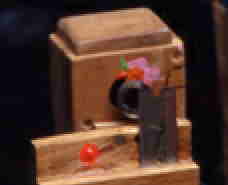 The first thing is to go through the theory of getting a camera to work. Remember that the camera is replacing the eyeball so you need to get the camera into the right place so that the light from the mirror that comes past the Knife Edge (KE) can bee seen by the camera lens. The problem here is to get a plain ol' physical alignment of the camera to the place that the light is coming past the KE. It just won't work if you handhold a camera very well as it is fairly difficult to hold the camera anywhere near steady enough to get a good photo and the next photo will be different from the first. The camera also really needs to be mounted securely enough so that it won't wobble about when the tester is moved about. This doesn't mean that you have to bolt the camera with a 2x4 block of steel to the stage but rather that the camera dosn't bounce about as you make adjustments but rather stays right behind the KE where it belongs. The photo to the right is what I've been using recently. It is a cheap security camera in the wood housing that I made that cost me $40 at one of the surplus places. It is mounted against the back wall of the box and the original lens was removed and the lens that is sticking out of the front of the box was attached. The 'finder' LED is presently on and the light is returned to the black box that is drawn on the right side of the camera housing so as to locate the mirror's return spot to the right place. Also note that when you use a LED rather than a laser, you have a nice discrete image of the LEd which is focused at that point as a laser will always indicate that it is a nice spot as that is all that the size of the beam from the laser is. When I turn off the 'finder' LED and turn on the Foucault tester LED the return from the mirror should impinge on the KE and into the center of the lens for the camera and the distance from the KE to the mirror should be very close to where the COC is of the mirror..
 Note in the photo that the lens is a simple lens that is merely epoxied to an aluminum tube. Inside the wood box is a cheap security camera module with the original lens removed from the lens holder and the aluminum tube setup so that it slides into the lens holder. These cameras have only an automatic gain control for the exposure so they are nice as there is no iris or aperture stop on the lens I used a lathe to make the aluminum tube to the right sizes, etc. Also note that you should paint the interior of the tube with a flat black paint. I used some model train paint (Floquil brand Engine Black which happens to be a nicely black paint that is fairly cheap in the little bottles that it comes in) to paint the inside of the aluminum to reduce the stray light that comes into the camera. The lens is about 1" focal length and works for mirrors down to about F5 (note that it is the focal ratio that is important in this as it determines the angle of the incoming beam and thus the amount of surface that is covered by that light return at the focal plane) without troubles of vignetting the mirror's image at the top or bottom of the screen.. A last thing to note is how close the lens is to the KE. It is almost touching the KE and is normally positioned so that half of the lens is blocked by the KE which puts the edge of the KE in the center of the lens and, when the light return is properly located by the 'finder' LED, the mirror's return is centered at the center of the lens. This camera is just sitting behind the KE on the base of the stand and leaning slightly towards the vertical part so that it stays there. It often slides about when coarse setup is being made and really should be tied to the stage so that it doesn't move about.
What is Happening in the Test.
 The drawing at the right shows what is basically happening with the edge rays from the mirror to the camera lens. Note that the lens in the drawing is some distance back from the KE so that the edge rays are at the edge of the lens. This is about as far back as you can contemplate having the lens and it should be even closer to the KE so that the rays enter the center part of the lens instead. When you pull the camera lens too far back, the edge rays can't enter the lens so they get missed and thus the camera can't see the rays from the edge of the mirror under test.
Another reason for getting the lens as close to the KE is that the light entering the edges of the lens often are vignetted to some degree by the optical train in complex lenses and thus the edges end up being darker than the central part of the lens, making the readings of the edges of the mirror highly dependant upon the centering of the light entering the lens - if the edge effects of the lens reduce the light to 75% of the light from the center out to the 75% zone of the lens, the edge ray from the mirror that is near the edge of the lens will start out being about 25% lower in intensity than the comparable ray that enters near the center of the lens, making your reading in error! Thus, in addition to everything else, try to make sure that when you are taking readings with a camera of any kind, try to make sure that the mirror is in the center of the image or you may be seeing an error of gray level which is being generated by the lens. Simple lenses like the one that I am using tend to have a smaller probability of an error with things like this. The simple lens also allows the lens itself to be physically close to the KE so that there is less of a cone of the light that needs to be captured by the lens. I can't emphasize enough that the closer the lens is to the KE, the easier it is for the lens to work well and capture all of the light. In addition, the usage of the central part of the lens by putting the lens as close to the KE as possible also reduces the possibility of this edge shading error.
What Cameras work well?
Any camera can be used for this test although certain cameras work better than others. Probably the poorest is the Camcorder type cameras as they usually have a small sized complex (usually a high range zoom lens) lens in front of the imager and there is often a built-in sunshade which restricts the ability to get the camera lens close to the KE. In addition, there is an automatic lens control for the F-Stop which causes problems with the placing of the lens close enough to the KE as that function essentially closes down the effective diameter of the lens, turning a 2" lens into a miserable 1/2" lens or less in the attempt to reduce the light on the imager. That function must be turned off and manual iris control used and set to the maximum opening possible. It is also wise to turn off the auto focus as that will often get miserably upset with the image that it is getting and won't focus well on the mirror. This problem also happens with manual lenses of all types when you close down the iris of the lens as what is really happening optically is that the effective diameter of the lens is decreased. Remember that if the focal length remains constant, the only way to change the F stop is to change the aperture that the lens is working at. Work with the aperture all the way open and you will get the best results. I'll also note that some of the camcorder lenses use a ND filter attached to the iris to maximize the range at which the iris works and this wil also cause a problem when it impinges on the image coming into the lens.
I prefer to use a video camera as the image rate on them is a nice quick rate and they plug into any TV that has the Viedo/Audio plugs in it. Cost of a security camera shouldn't set you back more than about $30 - $40 (many places can and will charge over $100 for the same cameras!) and you will need a $6 or so wall wart type power supply in addition. Seeing the Foucault test on a 25" TV is really a nice treat! Webcams will work better usually tho if you are planning on doing image capture of the test results or doing the RoboFoucault or other automated or semiautomated test.
Another way of making a case for the camera is to make a box with two pieces, the bottom carrying the back, camera and two sides and the top part carrying the front with the lens and two sides all setup so that the top part can slide to adjust the distance of the lens from the camera detector.
Webcams usually use the same micro lenses that the cheap small security cameras do (except for the pinhole cameras which have a small pinhole instead of a lens for doing the imaging) so the same system works for either. The lens is usually interchangable by screwing it out of the lens holder (don't forget to loosen the setscrew if there is one on the lens holder) and there is a 25mm focal length version (Edmund Scientific has them for about $50) if you prefer to go that way rather than making up your own lens setup. If you get a camera with a pinhole instead of a lens, just remove the pinhole box over the imager chip and use a lens instead with the enclosed box as described above.
Larger Video cameras for more professional security or industrial work also work well with their C-mount lenses, making sure that the lens surface itself it close to the KE, also work well and there are somewhat cheap zoom lenses available although the price on the cameras and lenses is cheap only to more professional equipment. Insure that the lens is of a fairly fast one and make sure that the iris is all the way open when you do testing otherwise you will end up restricting the light coming in with nasty results.
Any decent simple lens from a Plano-convex to a Bi=convex lens will work fine for the purposes of the camera as most of us use a color LED for the illuminant source. Since you are dealing with a single color, you can very nicely just use a single piece of glass as it will focus the single color of light perfectly onto the imaging surface. A doublet will also work fine but it will be more expensive to obtain compared to a singlet lens. If you have one floating around of the right focal length, feel free to use it tho. The closer that you can get it to the KE, the smaller the lens needs to be with the lens being right up against the KE being the best position possible for a minimal sized lens.
When it comes to the digital photo cameras, I'd suggest that only those with a preview display be used as you can then see if anything is going wrong with the imaging of the mirror. Also a problem with these cameras is just like that of the camcorders which is that they usually have a sunshade of some kind to protect the lens from the sun's direct rays. In addition, many have very small lenses which prohibits their usage for the purpose of handling the light coming past the KE. If you get one to work with your setup, feel lucky.
 One thing to note with any of the cameras that have a deep sun shade permenantly on them is that you can use a single biconvex lens to reimage the light from the KE to the camera lens. You want to mount the lens so that the distance is equal between the KE and the end of the camera lens. This will tend to reimage the KE right in front of the lens although it will be upside down and backwards as a single lens will do. Also note that when using LEDs for the light source, you don't need to do any color correction to the lens as there is only one color (provided that you're not using a white LED) that is being transmitted anyway.
Some Notes on Aligning a Camera for the Test.
I've noted that when setting up a camera, it is often necessary to insure that the center of the LED is being used for the source area that is going into the lens. I've found that the center of the LED on the slitless tester also happens to be the widest part of the LED and the other side is also a nice vertical edge. Thus, running the KE away from the beam return eventually hits the backside of the light source and thus you can see the way that the edge goes across the mirror. If the shadow is tilted one way or the other, you can compensate by moving the point of the mirror up or down until the shadow is fairly vertical and thus you will be in the fattest part of the source. With slits, you are in more difficult territory as all you can do is find the upper and lower edges of the source and use the mean between. Another way is to block off the center with a fine wire and look for that dimming of the image when you cross it as you move the mirror point up or down. The wire need not be accurately placed to a thousandth of an inch as the light source has a very finite size.
After you have determined the proper location for the light return to the KE and the lens beyond, it is wise to then mark the stage where the 'finder' LED returns the light to the stage and you should be set for putting the mirror's axis in the right place each and every time.

Afterword.
I'll note that after experience working with the tester, you will soon be able to setup a test with the camera in the space of 30 seconds or so and be taking data shortly thereafter. I have been timed by the grinders in the class that I have been running in San Diego area to setup the test on a fresh mirror and be taking data in less than 15 seconds, the timing having been unknown to me so I wasn't aware of any contest having been in progress.
If anybody has any questions, comments, feel free to email me. This subject is fairly new for amateur mirror makers and thus there may be a fair number of questions out there as to what can work. I hope that I have shown a number of ways to do a camera and explained the processes well enough that you can make your own decisions as to what you want to do and what is going wrong when things don't work out.