In the present installment of this series of articles, the author discusses method of protecting the telescope against the ravages of the weather, by building available shelters. With these protections, there is no need of removing a telescope from its accurately adjusted mount or changing the position of the mount.
 The amateur telescope maker soon tires of moving his instrument into the house or too-shed each night, when his observations are completed; and then he begins to think of ways of arranging things so that he can leave his telescope in position during its idle time. This is especially necessary if any accurate adjustment of the mount is attempted. The simplest and least expensive plan is a cover, which may be of wood, cloth or metal.
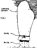
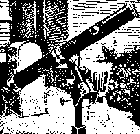
A tarpaulin of ample size thrown over the telescope, gathered in and tied around the pedestal, will give the necessary protection from weather. It is of little or no use against the bumps of children or animals, however. A telescope so covered is shown in Fig. 1. It should be turned to point to the zenith and all clamps tightened, before it is covered.
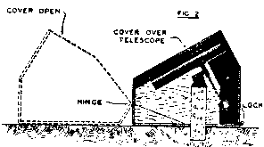
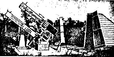
A wooden or metal box, which covers the instrument when it is not in use is a better protection. See Fig. 2. This is hinged to a fixed bottom section at the southern side; and may be lifted from the telescope and swung to rest on the ground to the south of the instrument where it is out of the way of the observer. In this case, before it is boxed, the declination axis should be placed in a vertical plane, with the telescope pointing towards the North Star. In this position, the counterweight is under the tube; and a comparatively narrow box may be used. A hasp and padlock up on the north lower edge will make all safe while the owner is away.
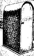
Another way is to place the telescope tube vertical and make a sheet-iron drum that will slip down over the mount and all. Oscar Marshall (one of the original Springfield Telescope Makers) boxed his 8 inch telescope this way. It required quite a large cover for this, too heavy to handle easily without help; so he fastened a swinging boom to the wall of his house. This was equipped with a rope and pulley and, with this apparatus, the cover could easily be lifted from the telescope, swung aside and placed where it would not interfere with the use of the instrument. One man could remove or replace the cover; it was fastened to the concrete telescope base by means of hooks and a padlock.
 |
 |
 |
 |
 |
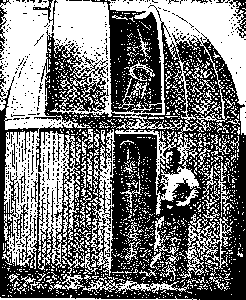
A number of amateurs have built permanent buildings to house their telescope. Some have a removable roof to allow access to the stars, while others have the conventional revolving dome and shutter.
 |
 |
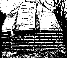
Fig. 8 is the observatory of G. F. Hofferberth of Dayton, Ohio, which measures 7 ft. 6 inch square. The dome is covered with composition shingles (pitched on the steeple pitch) and weighs about 6oo pounds. The shutter covers a slot 2 feet wide. The whole is painted with aluminum paint and makes an imposing home for his 6 inch telescope.
 |
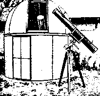 |
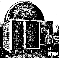
Fig. 10 is the work of K. F. Davison of Marshfield, Wis. Mr. Davison is a photographer when not making telescopes.
It is necessary that the slit should be movable, so that the telescope can be pointed to any part of the sky. This is usually accomplished by having the dome revolve on a circular track on wheels. In several cases, however, where circular buildings have been used, the entire building revolves.
Individual design in domes may vary in many ways. A simple one will be described and you can fit it to your needs, adding all the gadgets that your favorite junk dealer may be able to supply.
The walls of the building (rectangular or round as you may desire) must bear on the top a ring of circular plate. This plate may be built up of several thicknesses of boards, screwed together with the joints 'broken'. the inside diameter of the plate should be at least 7 1/2 feet, and this should be rounded accurately.
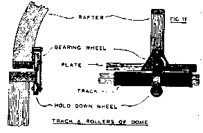
The track should be about 1/2 inch wider than the thickness of the plate and 1/4 inch thick. If the plate is 1 1/2 inch thick, the track may be made from 1/4 x 2 inch flat steel. It should be bent accurately to the curve of the plate to which it is fastened with screws. In making the dome, another circular plate is made and the rafters rise from this. To this plate are fastened a number of grooved pulleywheels to run on the track, allowing the dome to revolve.
 |
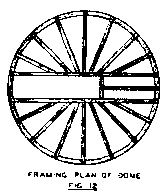 |
In framing the dome, first run clear through it two semicircular rafters, 2 feet apart, to frame the slot. The other rafters are cut into these like the longitude lines on a map. The slot should extend beyond the top of the dome, far enough to allow the telescope to point to the zenith.
Fig. 12 suggests the framing of a dome. The rafters may be cut from wood one inch thick. The dome may be covered with either canvas or sheet aluminum to reduce the weight. The slot cover may roll up, if made of canvas; or slide sideways, if of metal or wood in one piece. It may also be made in several pieces, and slid vertically like a window sash; it may be hinged either as a whole or in sections. The accompanying pictures show what other amateurs have done. Now, see what improvements you can work out for yourself.