In the earlier installments of this article, appearing in the last two numbers of Everyday Science and Mechanics, we learned how to grind and polish the concave mirror for a reflecting telescope, and how to give its surface the parabolic contour necessary to obtain the best definition. A simple altazimuth mount was also described; this is convenient for use in observing scenery or other terrestrial objects. However, for most effective use on the heavenly bodies, a telescope should have an equatorial mount.
Everybody knows that the Sun "rises" and "sets" every day; and of course you also know that this is only an apparent motion, really being caused by the Earth's rotation on its axis once in 24 hours. It necessarily follows that all the heavenly bodies have a similar apparent motion, rising in the east and setting in the west approximately every 24 hours. If one axis of the telescope mount is placed parallel to the Earth's axis, and the telescope is revolved from the east to the west on this axis, at the same rate that the Earth turns, the star under observation will remain stationary in the telescope; otherwise it will appear to move rapidly across the field in the eyepiece, and soon disappears.
Since the Earth turns through 360 degrees (a whole circle) in 24 hours, it turns through 1 degree in 4 minutes. The Sun and Moon each subtend an angle of about half a degree; so you can see that the heavenly bodies appear to move a distance equal to the Moon's diameter in about two minutes. As a high-power eyepiece will take in only a small part of the Moon at once, constant adjustment of the telescope is necessary.
To sum up, the equatorial mount differs from the altazimuth mount by having one axis, named the polar axis, parallel to the Earth's axis; while the other axis, called the declination axis, is at right angles to the polar axis.
 |
 |
 |
 |
 |

 |
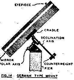
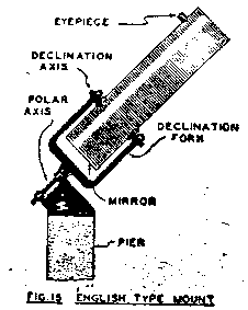
The English, or fork type, mount is shown in Fig. 15. In this mount the telescope is hung on trunnions in the fork with its center of gravity at the point where the center lines in balance in all positions without any counterweight.
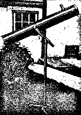
Fig. 16 is a photograph of a German type mount made by an amateur. Fig. 17 is a photograph of an English type portable mount. With this mount, as illustrated, it is impossible to point the telescope towards the Northern sky; but if the fork is made deep enough to allow the mirror end of the tube to swing through, as in Fig. 15, it will reach all parts of the sky.
The mount which is illustrated on Part 1 of this series of articles is a modification o the German type mount. In this, the telescope, instead of being hung at its center of gravity, is placed with the eyepiece in line with the declination axis. This requires an offset counterweight in order to balance it. The great advantage of this mount is that the change in position of the eyepiece, which occurs when the telescope points to different parts of the sky, is much less than when the eyepiece is located as in Fig. 16.
On a map of the Earth, or on a globe, places are located by their latitudes and longitudes. In the sky, a similar system of circles is used. The poles of the heavens are over the poles of the Earth, and the celestial equator is over the Earth's equator.
The declination of a star is its angular distance north or south of the equator, and corresponds to latitude on earth. A declination circle divided into degrees is frequently placed on the declination axis of the telescope.
Right Ascension: on the Earth the equator is divided into degrees of longitude, starting with zero at Greenwich, England; but the sky it is more convenient to divide the equator into 24 hours, and those into minutes and seconds. The starting point has been taken at a point on the celestial equator called the Vernal Equinox; and half of a great circle passing through the Vernal Equinox and the poles is called the Zero or 24 hour circle. Just as 12 and 0 are the same on an ordinary clock face; for astronomical time runs up to 24 hours.
When we say a star is located at Declination +32"12' and R.A. 14 hr. 23 min. 18 sec. we mean that it is 32" 12' north of the equator (plus being north and minus being south) and that in 14 hours, 23 minutes and 18 seconds it will be in the position now occupied by objects having 0 or 24 hours Right Ascension.
The Right Ascension circle is placed on the polar axis, and a worm gear on the polar axis turned by a worm is used to move the telescope, when following the stars. This is sometimes connected by gearing to a clock or a synchronous electric motor, to give a continuous motion, holding the star stationary in the field. This is especially necessary when long-time photographs of star fields or nebulae are taken.
A worm gear on a screw feed on the declination axis is a help in bringing a start to the center of the field, or in making accurate settings on the graduated circle.
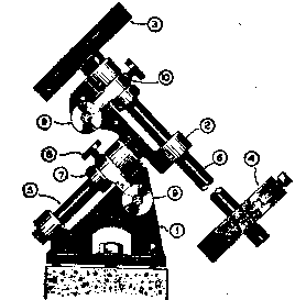
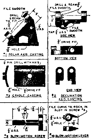
Figs. 18 and 19 are working drawings of a very simple equatorial mounting that performs very satisfactorily. The castings may be purchased ready cast, or patterns may be made and modified to suit the location and whims of the designer; from these, castings may be made at any foundry.
The base (1) should be made so that the polar axis lies at an angle from the horizon equal to the latitude of the place where the telescope is to be used. If special castings are to be made, this should be included in the design. Standard castings are made at 45 degrees, and the polar axis is given the proper position by the adjusting screws in the base or by casting the top of the pedestal at an angle. The telescope is bolted to the cradle (3) at it's balance point, and is balanced on the polar axis by the counterweight (4).
Slow motion is obtained by means of the slotted screws (9) acting on the fingers (10) which are clamped to the axis by the clamp screws (8). For quick movements, the screws (8) are loosened, allowing the axes to turn freely.
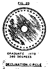
If circles are desired, the declination circle is screwed to the cradle boss; it is made as shown in Fig. 20. A 4" circle of 1/16" thick brass is divided into 360 divisions. Every tenth one is stamped; from 0 to 90 and back again to 0, and then repeat. The circle is fastened on the boss and a pointer fastened to the declination casting in such a position as to read 90 when pointed at the celestial pole, near the North Star.
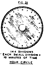
The Right Ascension circle may be screwed to the boss of the declination casting, with its pointer fastened to the Polar axis casting. The R. A. circle, shown in Fig. 21, should be located so that it reads 0 when the telescope points south and 6 when it points either east or west. The circles are not necessary or even desirable when you start out as an observer. Make your mount as simple as possible to start with; and add features as you feel the need of them.
When the telescope is attached to the mount, it is necessary that the axis of the tube be at right angles to the declination axis of the mount. This may be tested, as follows:
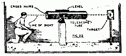 Fig. 22 shows the setup for this test. Hold the head at least 5 feet back of the crossed strings, so that those on each end will be in clear focus of the eye. Remove the crossed strings from the mirror end of the tube and replace the mirror. The mirror is adjusted by its screws until the front cross strings line up with their reflection at the exact center of the mirror when observed from a point several feet in front of the open end of the tube.
A diagonal mirror cannot be lacquered satisfactorily. The mirror can be lacquered, because the "soap-bubble" caused by the lacquer combine in the image to reproduce its original colors: since light comes from every part of the spectrum to every part of the image. By the time the cone of rays reaches the diagonal, however, they have localized sufficiently to reproduce roughly the streaks of lacquer color, on the diagonal, in the field of view of the eyepiece. If you observe a large white object, such as a white house, or the moon, you will get a color pattern certainly not on the original.
If your diagonal is really flat, and the silver bright and unlacquered, it will give excellent results. When selecting the glass for a diagonal, collect all the broken mirror glass, windshield or other plate glass about 1/8" thick, that you can find, and cut it into rectangles the size you desire. For a 6" telescope they may be 1 1/8" x 1 7/8" in size. Clean them and press them together by pairs and observe the interference bands, which are visible by monochromatic light.
A suitable light is that of an alcohol or gas flame on which ordinary salt is sprinkled. the intense yellow flame shows the characteristic yellow of sodium, and is excellent for this purpose. A screen of tracing, or other translucent, paper is placed in front of the light to diffuse it and give a large surface.
Now place a pair of your glass rectangles in front of the screen, and observe as shown in Fig. 23. A series of black and yellow lines, caused by interference of light reflected from the two surfaces in contact, will be seen. Press one edge of the glasses, until they are as nearly straight as possible and are about 1/4" apart. If the lines are straight it indicates that the two surfaces are parallel to each other; in other words, that they are alike. They may both be flat; but also, one may be convex and the other concave to the same amount. To be sure that they are the flat surfaces that you desire you must test various pairs together until you find three surface that, when tested (1 with 2, 2 with 3 and 1 with 3) give in all cases straight lines. When you have done this you have three flat surfaces; because you can readily see that the only possible surfaces that will be parallel when combined in this way are flat. Mark the wrong sides with a glass cutter or paint to distinguish them. Silver the good side of one, and use it instead of a prism.
If the readers of this magazine are interested enough in these articles to write in and may so, the series will be continued; and the making of less simple telescopes such as the Cassegrain or even the refractive type will be taken up. Other possible subjects are the making of small lenses, etc.