 The combination will be positive; for, owing to the high dispersive power of the flint glass, the negative lens will be only about half as powerful as the positive lens when their dispersions are equal in amount.
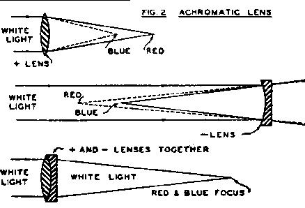
The index of refraction of glass is a measure of the amount to which light is refracted or bent in passing through a lens or prism made from this glass. It is not the same for light of all colors; red being refracted more than blue and each color somewhat differently. So that light rays, after passing through a lens, will not all come to the same focus of the blue being (for a positive lens) nearer the lens than the focus of the red. Since ordinary light is a combination of many colors, you can readily see that a single lens would not make a good telescope objective.
The difference between refractions, of the red and blue light, by a certain kind of glass is known as it's dispersion. this not the same for all kinds of glass; a flint glass lens or prism dispersing the light about twice as much as a similar lens or prism of crown glass. An achromatic lens is made by combining a positive lens of crown glass with a negative lens of flint glass having the same amount of dispersion as the crown. Since the flint lens is negative, it's dispersion is opposite to that of the positive crown lens; and when we combine them their dispersions are neutralized and the red and blue rays come to the same focus. (Fig. 2)
The combination will be positive; for, owing to the high dispersive power of the flint glass, the negative lens will be only about half as powerful as the positive lens when their dispersions are equal in amount.
In calculating an achromatic lens a great deal of advanced mathematics may be used; but we shall do very will by certain simple "rule of thumb" methods.
First we must get our crown and flint glass. It is well to use the kinds of glass recommended by the dealer as suitable for telescope objectives. With the glass he will supply the index or coefficient of refraction of each kind of glass, and another characteristic known as the V value. If the dispersion is not given separately we find it by subtracting 1 from the coefficient of refraction (ND) and dividing the remainder by the V value.
For the sake of simplicity we will make our objectives with both curves of the crown glass and the first curve of the flint glass, equal. (R1 equals R2 equals R3). If we make the radius of this curve 0.4 of the desired focus of the achromatic lens with ordinary types of glass, we will get very nearly the desired focus of the combination when we have made our last surface of the curve that will give us an achromatic combination.
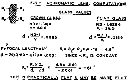 If the dispersion of the flint is just twice that of the crown glass, the last surface of the flint lens will be flat; if less, this surface is concave; and if more, convex.
The radius of curvature for the forth surface is found by multiplying the radius of the first surface by the dispersion of the flint glass, and dividing the product by the difference between the dispersion of the flint and twice that of the crown. In Fig. 1 is the computation for a lens of 12 inch focal length is carried out.
In the above chart, the calculations for a lens of 12 inches focal length are carried out. The reader will find that, by following the rules laid down in the article, and the system of arriving at the results, he can calculate the correct curvature for a lens of any required diameter.
After the lenses have been ground, polished and centered, as described in the December issue of this magazine, they are cemented together with Canada balsam, dissolved in xylol or acetone, which makes a permanent joint. A little cement is placed between the lenses which are then placed on a sheet of asbestos and heated over a gas or alcohol flame until the balsam flows out all around the edges. They are then allowed to cool. The joint should be perfectly transparent. If there are imperfect places, reheat, separate them; clean with turpentine and then soap and water; and try again.
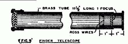 The finder telescope is a relatively simple construction made as in the above diagram. The principal of manufacture is the same as the larger telescope; and details for building are also included in the present installment of this series of articles.
Fig 3 shows a finder telescope with an achromatic objective. As in all telescopes, the focal plane of the objective should coincide with that of the eyepiece. The cross-wires are also placed at this common focus. To make the cross-wires, cut out a washer-shaped diaphragm, large enough so that when pressed into the telescope tube it will remain where placed. Punch or drill for small holes equally spaced, and thread through them a fine copper wire crossing at the middle of the washer. Blacken the wires by heating them with a match. A single lens eyepiece is shown, but of course and kind may be used.
If it is a Huyghenian, the cross-wires should be placed on the diaphragm between the two lenses of the eyepiece. This may be pushed from the eyepiece tube and replaced after fitting with wires. If the eyepiece is of the Ramsden type, the crosshairs are placed in front of the field lens of the eyepiece. In any case the crosswires should be in perfect focus when observed through the eyepiece.
The forgoing instructions are applicable to small objectives only. Where the diameter is over 2 inches, it is advisable not to cement the crown and flint lenses together, but to separate them slightly. The amount of separation is determined by trial; that separation giving the least color to the image being selected. A correction for spherical aberration is also made, where the best definition is necessary.
The making of a 4 inch objective will now be described. The methods used are applicable to larger or smaller sizes.
A focal length of about 15 times the diameter of the lens has been found to give the best results. It avoids the excessive spherical aberration of shorter focus lenses and is not so long that the illumination of the planets or nebulae suffers unduly.
We decide on 15x4-60 inches for the focal length of our objective, and compute the curves as described for the smaller objective in the first part of this article.
We will run through these computations for an objective made from Jena glass with the following characteristics:
| Crown - | Nd = 1.516 | Vd = 64.0 | D = .0081 | ||
| Flint - | Nd = 1.620 | Vd = 36.4 | D = .0171 | ||
| 1. | R1 = R2 = R3 = | .4x60 = 24 inches. | |||
| 2. | R4 = (R1 x Df) / (Df - | 2Dc)= (24 x .0171) / | (.0171 - .0162) | ||
| = (24 x .0171) / .0009 | = 456 inches convex. |
A lens of this size or one requiring extreme accuracy should never be ground or polished on a rotating lap. It has to be hand ground and polished in the same manner as the concave surface of the mirror of a reflecting telescope. Beside the crown and flint disks we must have two plate glass disks of the same size for tools. Place the crown disk on the workbench and fasten it by driving three nails around it. Hold one of the plate glass disks in the hand, and, using the stroke and motions described in the September issue of this magazine, rough grind the crown disk to a curve of 24 inch radius, as determined by applying a template to the curve.
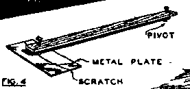 The template is made as follows: drive two nails through a wooden strip 24 inches apart. One nail is driven through into the workbench, and serves as the pivot on which to turn the strip. A piece of tin or sheet zinc is placed under the other nail and, by swinging the strip around the fixed nail, a curve of 24 inch radius is marked on the sheet metal, which is then cut out with shears to serve as a template. (see Fig. 4)
When surface 1 is rough ground to fit the template, the crown disk is turned other side up and ground with the flint disk as the tool to the same curve. It is advisable to lay the crown in a wooden circle or to gouge out the board under it so that it will lie firmly and not rock on the surface which is first ground into the glass.
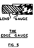 As rough grinding nears completion, remove the crown disk from the bench and measure the edge with a caliper made by filing a notch in a piece of 1/16th inch sheet brass to fit the edge of the lens as shown in Fig. 5 You will probably find one part of the edge thicker than the other; and this must be remedied by turning that edge of the lens toward you and pressing hardest at the beginning of the stroke in grinding. When the edge measure the same all around you are ready to fine grind.
Fine grind just as you did in making your concave mirror, using a short stroke (about an inch from end to end) with graduated grades of abrasive from the coarsest No. 120 to the finest No. 600; and polish on a pitch lap with optical rouge in the same manner that you polished your mirror. The center of the lap should be reduced in area to encourage the oblate spheroidal figure on the polished surface, as this makes later corrections much easier. (Fig. 6) Also be sure to trim the edge of the lap, making it about 3 3/8th inch diameter for the 4 inch lens to avoid a turned down edge.
It is immaterial whether the lens or the lap be held in the hand; but if the lens is on the table it should be turned at frequent intervals; or better, hold it on a barrel or pedestal so that the worker can move completely around it while fine grinding and polishing.
Before starting to polish, check with the edge gauge and be sure that the edge is the same thickness all around. Place clean paper under the lens, to avoid scratches on the finished surface. After polishing the crown lens, a new lap - convex - is made and the third surface is polished.
Next a new tool is selected and the fourth surface is ground and polished. We found that it is to be convex, with a radius of 456 inches. Using our old formula; depth = r^2 / 2R we get 2x2 / 2x456 or 0.0044 inches for the height of the convexity or the depth of the hollow in the tool. This is just about the thickness of the cover of this magazine; so, placing the flint disc on the workbench with the fourth surface up, grind until you can just slip a corner of the cover of this magazine under a straight edge laid across the tool.
For this slight depression it is better to rough grind with No. 2 grit - the 120 grain - rather than the coarser No. 80 ordinarily used. If the disc is badly wedge shaped, as they sometimes are, you can save time by grinding it down to an even thickness before starting. In any case, the flint should be of the same thickness as the crown before starting. When find grinding is completed the edge should be the same thickness all around as tested with an edge gauge or a micrometer. Then polish the fourth surface. this completes the lens, except for adjustment and figuring of the fourth surface for spherical aberration.
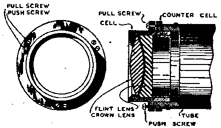 Before carrying out the final corrections, we will make a cell and tube for our objective. Make the cell and ring from aluminum or brass on a lathe, as shown in Fig. 7. It is made extra deep so that the two lenses may be separated if it should prove desirable to improve the achromatism of the objective.
The tube may be made of bras 5 inches in diameter by 50 inches long. The counter cell is fastened permanently to the tube. The cell is removable and has three pairs of push pull screw to square it on the axis of the tube.
Place the lenses in the cell with a ring of heavy paper between them. Do not drill the retaining ring for screws until later. The friction between the ring and the cell should be sufficient to hold the lenses in place while testing. You may also leave the push screws our of the cell flange until ready to square on the objective.
Assemble the tube and counter cell and the cell with its contained objective; and prop it up on a table so that it points at some distant light at least a city block away. the smaller the object and the greater the distance, the better. A star would be best if it would keep still long enough. Looking at this light through the tube, move the head back until the light expands and covers the entire objective and at this place setup up your knife-edge for testing by the Foucault method; just as you did with your mirror, as explained in the October issue.
Adjust to give the characteristic shadows. If the objective darkens evenly all over when the knife-edge cuts the cone of rays, your objective is perfect, so far as spherical aberration goes at least; but probably you get the parabolic or oblate spheroidal shadows you learned to recognize form the before mentioned article. These must be eliminated by polishing the fourth surface of your objective to give the flat shadow that, in the case of the mirror, indicated a spherical curve. If the shadows indicate a hill at the center, remove the flint glass and polish with a long stroke until the correction is made as indicated by replacing the lens and testing as before.
If, instead of a hill, you have a hollow, remove from the center of the lap a star shaped area and polish until the hollow disappears. If there is doubt as to whether it is a hill or a hollow, touch the lens at the center with the hand for a minute. This will cause that area to expand with the heat from the hand. Then observe The shadows and, if the effect is increased, it was a hill. If, on the contrary, the expansion has counteracted the defect observed you know that it is a hollow and can act accordingly. If there was a turned down edge, reduce the diameter of the lap and polish until the effect disappears. If the effects are too great, it may be necessary to correct other surfaces besides the fourth. If, after several hours' work, you have made little progress, try another and another until you have produced an objective free from spherical aberration - one that darkens evenly all over as the knife edge cuts in at the focus.
 If you are so fortunate as to have an optical flat as large as your lens, you can use the Auto-Collimation method of testing, which allows the entire process to be done indoors.
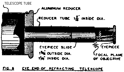
Before the tests and adjustment for achromatism the telescope should be completed by constructing and putting in the eyepiece slide, as shown in Fig. 8. The distance from the objective to the focal plane of the instrument is the distance from the objective to the knife-edge in testing on a distant light. Measure this distance and make the reducer tube of sufficient length to extend to within 1/8th of an inch of the focal plane. The eyepiece slide carries the eyepiece and is used to focus it.
Some form of mount must be provided before proceeding further; that shown in the November article is very good. The pedestal should be about 6 feet high, for comfort in observing objects near the zenith.
We are now ready to square on the objective; that is adjust it so that it's optical axis passes through the center of the eyepiece. To do this we point the telescope at the North star and focus very carefully, the North Star is chosen because it will not move rapidly out of the field of sight, as stars further south do, unless the instrument is move to follow them.
You will probably find that, instead of a small round point of light, the star image is fan or pear shaped; the smaller end being the brightest. This indication that the objective is too near the eyepiece on the side corresponding to the small bright part of the image. With a piece of crayon mark the telescope tube on this side; then, using the push-pull screws, move the side of the cell further away from the counter cell (or the opposite side nearer) and look at the star again. Repeat until the image shows as a round dot. If the image is thrown a little out of focus by moving the eyepiece in or out, it should expand into a perfectly circular area made up of concentric rings.
Sometimes several of the lens surfaces may be astigmatic; that is, the radius of curvature may be different along different diameters of the lens. This condition is shown by elliptical images and rings when the image is thrown out of focus. They remain elliptical even when squaring on is as perfect as can be accomplished. To correct this appearance, try revolving the flint lens on the crown, testing it on a star in a number of different relative positions, and choosing that position which gives the most truly round image and ring systems. when this is found, make a pencil mark across the edges of both lenses so that they can always be replace in this position. When the objective is thus adjusted for astigmatism, and perfectly squared on, we can examine the image for achromatism.
In this, as in squaring on we use a 1/4 inch efl. eyepiece and examine the image of the North Star. If the objective is a good one the image should be greenish yellow in color surrounded by a very faint violet halo.
Different separations of the crown and flint may be tried, by changing the thickness of the spacer between the lenses; and that separation is chosen permanently which five the image with the least halo around the star. Be sure to mark the cell and counter cell, and also the edge of the crown and flint glasses, so that they may all go together in the same way each time you assemble the lenses.
Now drill and tap for the screws that hold the lens retaining ring. Screw it in place, reassemble - and your telescope is complete. You will, some time, want a rack and pinion focusing device instead of the simple slide described, and will probably elaborate an perfect your mount as time goes on. However, the simple instrument described will give excellent service, and you should not attempt too pretentious an outfit to start with. Let your telescope grow as your knowledge expands, and you will learn what you really want and need.
By means of this arrangement, adjustment of the lenses of the telescope is readily made. the push screws are threaded into the cell and push against the countershell. The pull screws pass loosely through holes in the cell and are threaded into the countercell. These two screws permit any side of the lens to be either pushed in or pulled out.