
In discussing these compound reflectors, it is assumed that the reader is familiar with the construction and testing of the simple reflecting telescopes described in earlier articles of this series.
A more popular way of obtaining the magnification which goes with a long focal length, without its drawbacks, is to use a second mirror to enlarge the image formed by the mirror, before the eyepiece gives the final magnification.
Two methods are possible; one by using a second concave mirror as in the Gregorian telescope; the other by using a convex mirror as in the Cassegrain telescope. Both of these will be described.
 |  |
Fig. 1 is the diagram of the Gregorian telescope. The great mirror receives light from an object, and reflects it to a focus at F. A smaller concave mirror with F' as one conjugate focus forms an enlarged image at f, the other conjugate focus. For convenience, we usually have f some distance back of the mirror which has a hole cut to allow the light to pass through. The eyepiece is placed here, and still further magnifies the enlarged image formed by the secondary mirror. The magnification by the secondary is usually from 4x to 8x. In our example we will chose 5x, as being at neither extreme. The image f will be 5x as large as it is at F, and the distance D will equal 5d.
We will compute a 12 inch Gregorian of 20 foot focus. This will give, with a 1/4 inch eyepiece, a maximum magnification of 4x20x12 or 960x. Since the magnification by the secondary is 5x, the focal length of the mirror will be 20/5; that is 4 feet or 48 inches. If we place the eyepiece 6 inches behind the face of the mirror, distance D-d (f to F) is 48+6 or 54 inches is equal to 4d, and e equals 13 1/2 inches. D, which equals 5d is then 67 1/2 inch.
If we allow the telescope tube to project 6 inches beyond the secondary mirror, the total length of the telescope would be only 73 1/2 inch, instead of the 20 foot length needed for a Newtonian of the same power.
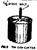 First we make the mirror, 12 inch diameter by 48 inch focal length, and parabolize it in the ordinary way. After parabolizing the hole is cut as follows: make a cutter from a tin can and bolt, as shown in Fig. 2. The can should be slightly smaller than the secondary mirror; this so that the turned up edge (which will appear when the hole is cut) will be covered by the shadow of the secondary and so will not be part of the working surface of the telescope; a 2 inch diameter will be suitable. Grip the bolt of the cutter in a drill chuck, and place the mirror face up on the drill table. Rotate the cutter on the glass with medium grit and water, raising and lowering the cutter frequently to allow circulation of the grit and water. It will take about an hour to cut through. Melted paraffin painted on the mirror for protection, and three sticks clamped on to guide the cutter, are advisable.
The concavity of the secondary mirror is computed from the formula:
| Radius of curvature r = 2Dd/D+d. | |
| Substituting our values for D and d, we get: | |
| r = 2x 57.5 x 13.6 / 31 = 22 1/2 inch. | |
| The diameter of the secondary mirror can be found from the formula: | |
| Diam. = (Ad / f) + (ad / D-d) | |
| Where A is the diameter of the mirror and a is the diameter of the largest field lens in any eyepiece used - say 1 inch; substituting we get: | |
| Diam. = 12 x 13 1/2 /48 plus 1 x 13 1/2 / 54 = 3 3/8 plus 1/4 or 3 5/8 Inch. | |
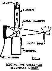 It is easily and accurately tested by setting up the artificial star at F and the knife edge a f (Fig. 3), and then polishing out the center until a uniform "flat" shadow shows in testing. Any of the standard parabolizing stroked may be used - long stroke, overhung mirror, or a lap cut away at the edges. Since the testing lamp is too large to place at F, we will put a polished steel ball there, to reflect the light from the electric bulb located out of the range of sight, at one side. Screens, or paper tubes, painted black, should be placed to keep the light from the operator and the room at large. Be sure that the distances from the secondary to F and f are equal to d and D respectively.
In assembling, provision should be made to adjust the small mirror both towards and away from the primary mirror; so that the position of F at the eyepiece can be brought to the desired place. It must also be so arranged that it can be tipped as necessary to bring its axis in line with the axis of the mirror.
To adjust after assembly proceed as follows:
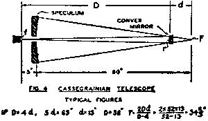
In the Cassegrain, magnification by the secondary mirror is usually from 3x to 5x. For our example, we will compute a 12 inch Cassegrain of 20 ft. focus as we did with the Gregorian. We will make our secondary magnification 4x, and the eyepiece will be 5 inches back of the face of the primary mirror.
First make the primary mirror and parabolize it. The focal length of the primary mirror will be one-fourth of 20 ft. - that is 60 inches. The distance from f to F is 65 inches which (from Fig. 1) equaled D+d or, since D = 4d, 65 equals 5d; d is 65/5 or 13 inches, and D is 4x 13 or 52 inches. Adding 6 inches for the telescope tube to overhand the secondary mirror, out total length is 58 inches. The distance from the primary mirror to the secondary mirror is 52 - 5 inches or 47 inches.
The curvature of the secondary mirror is given by the formula:
| r = 2Dd / D-d. | |
| Substituting r equals 2 x 52 x 13 / 39 = 34 2/3. | |
| The diameter of the secondary is given by the formula: | |
| Diam. = (Ad/F) + (ad / D+d). | |
| Substituting: | |
| Diam. = (12 x 13/60) + 1 x 13 / 65 = 2 3/5 + 1/5 = 2 4/5. | |
Cut out the secondary mirror and its tool from plate glass, grind and polish in the usual way - except that, in rough grinding, the mirror is the under one of the two glasses. Polish with a short stroke. Check the radius of curvature, by putting a ten-minute polish on the concave tool and setting up the testing lamp and the knife-edge at its center of curvature. See the October issue of this magazine. It should be 34 2/3 inches from the mirror to the artificial star and also the knife-edge.
The secondary mirror will, when finished have neither a parabolic or elliptical curve, but a hyperbolic one; this being necessary to bring all rays of the intercepted cone to as accurate focus at f.
We will describe two methods of testing this curve: one in connection with the primary mirror and a large flat mirror; and the other the recently invented method using a spherical mirror and testing the secondary without using its mirror.
In the first method we need a large flat mirror - at least as large as the primary mirror. In the April issue of Everyday Science and Mechanics, instructions were given for the making of such a flat.
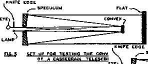 The setup for testing is shown in Fig. 5. The mirrors are placed in the same relative positions as they will occupy in the telescope, with the large flat in front. A lighted pinhole and a knife-edge are placed in the focal plane of the telescope. The light passes to the convex, then the primary mirror; then, as parallel rays (since the lap is at focus) to the flat, which returns it over a smaller path to the knife-edge, where the shadows are observed.
Since there are five reflections, the primary mirror and flat must be silvered to save light. The setup must be carefully made if the final image is to come back to the knife-edge. First setup the primary mirror and, in place of the convex, put a wire ring having cross-wires. Adjust the primary mirror until the wires and their reflections line up with the center of the hole in the primary mirror when viewed from about 10 ft. in front. Next put cross wires across the hole in the primary mirror and set up the flat; adjusting it so that the two sets of wires, their reflections of the eye all line up when observed through the center of the hole in the primary mirror, and adjust it to bring the image of the primary mirror central when seen through the hole in the primary mirror. Place the convex mirror, and adjust it to bring the image of the primary mirror central when seen through the hole in the primary mirror. Cover the flat with paper while adjusting the convex mirror. Finally place the lamp and knife-edge, and make any final necessary adjustments with the flat. If the focal point is not at the right distance behind the primary mirror, shift the convex mirror along the optical axis until the focal plane is where you want it.
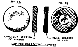 Usually, the shadow seen at this time is our old friend the doughnut; but with this test we want a flat shadow, like that of a spherical mirror tested at the center of curvature. The raised zone must be polished down (Fig. 6A) with a ring lap (Fig 6B); using very cautious short strokes and frequently testing until the desired even shadow is obtained. If some contour different from the doughnut is obtained, it is corrected in a similar way, cutting the lap to wear down the high places to produce a flat shadow.
When you get the flat shadow, the secondary is correct for this particular primary mirror at this particular separation. If the distance between the primary mirror and the convex mirror is materially changed, the required hyperbolic surface of the convex will be different, and refiguring will be necessary.
A recently invented method of testing the Cassegrain convex does not require the large flat mirror, or even the primary mirror and also the distance d and D, Fig. 4.
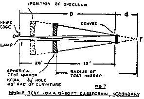 In this method a short focus spherical mirror is made and setup, as in Fig. 7, with its center of curvature at the point F, where the focus of the primary mirror will come. The radius of the spherical mirror must be not greater than the focal length of the primary mirror.
If it is made exactly this length, the size of the spherical mirror will be equal to that of the primary mirror and it will occupy the position of the primary mirror in relation to the points F and f and to the convex. This, however is unnecessary as, by making its radius shorter and placing it nearer to the point F, it may be made considerably smaller than the primary mirror, at a saving of cost and effort.
In Fig. 7, light from the testing lamp at f falls on the convex mirror and is reflected as a cone of light apparently diverging from point F. These rays strike the silvered spherical mirror whose center of curvature is also at F, as radii; and so are reflected back upon themselves to the convex and then back to the knife-edge where the resulting shadows are observed just as in the test shown in Fig. 5. The secondary is corrected to give the uniform shadow required in the former method and in the same way.
In this method of testing there are only 3 reflections; at the convex, at the spherical, and a second at the convex. In the test with the flat there are 5 reflections, convex, primary mirror, flat, primary mirror, convex.
The saving of light lost by the two extra reflections gives shadows more easily seen. Another great advantage of the new method is that imperfections in the convex mirror are doubled is intensity because of the two reflections there, while imperfections in the spherical concave are only half as apparent, on account of the single reflection there.
 | |
 |
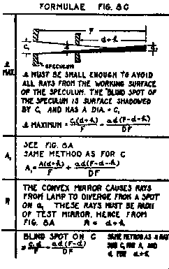 |
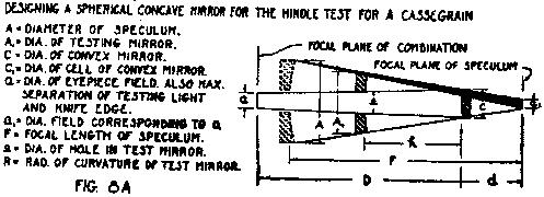
 The dimensions on Fig. 7 are suitable for testing a 12 inch, 20 ft. Cassegrain we have designed. The actual diameter needed is 9 inch, but we will use a 10 inch disc to allow 1/2 inch of non-working edge. At minimum, e is 1.7 inch; and maximum, 2.2 inch. We actually make our hole 1 3/4 inch diameter, allowing a non-working zone 1/4 inch wide around the hole. This should be ample.
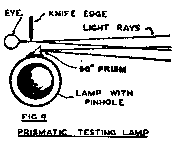
In these tests it is necessary that the artificial star and the knife-edge should be very close together. A convenient way to accomplish this is by means of a prism mounted in front of the pinhole, as in Fig. 9.
			Fig. 8D
A=12"    F=60"    D=3d    D+d\F+4     G=1"
These 5 given values define the optical train.
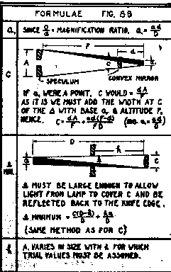
	D+d=64=4d   d=16"   D=48"    G=1x16/48 = .33
	C=16x12/60+16x44/60x64 = 16/5 + 11/60 = 3.2+1.6=3.38"
	C1=c+2xcell rim = 3.38+.22 (assumed) = 3.6"
 ______________________________________________________
assume h=24"
	*min. = 3.38x24/48+1.69"
	*max. = 3.6x40/60 - 16x20/48x60 = 2.4-.11=2.29"
	*margin=2.29" - 2.19" - +0.1"
	A = 16x40/60+16x20/48x60 = 8.11"
By making L less than 24" we could make *min - *max and A less than 8.11" but to
avoid effects of imperfect edges we increase L to give more margin around the and us a
9" test mirror, making A about 8.5" not using the outer 1/4"
_____________________________________________________
Assume H=26"
	A1=8.4+.1=8.5"
	*min.= 2.09"
	*max = 2.42"
	Margin = 2.42 - 2.09 = .33"
Make * 2 1/8".  This allows .03" on *min but most of the margin - .3" - is allowed
for a poor edge around hole *.  .15"= width of idle zone inside of *max.
_____________________________
	Conclusion
  Use a 9" spherical mirror of 42" radius with a 2 1/8" hole.  Set 26" from
the convex mirror.
Note: The image of this table was so poor that I copied it as best possible and am displaying here as text rather than an image. Bob