From the Monthly Notes of the Royal Astronomical Society (1965) Vol. 216 pp 411-427
1. Introduction
A three-mirror telescope was recently describe (Willstrop 1984a, hereafter Paper 1) which relies on the optical properties of coaxial, confocal paraboloidal mirrors (Mersenne 1636) and the Schmidt camera (Schmidt 1931).
It was shown to have ray-theoretical image spreads under 0.31 arcsec. over a field 4° in diameter, or (with slightly different asphericities of the mirrors) under 0.05 arcsec over 2°, and the focal surface is only moderately curved. The basic form, consisting of a concave paraboloidal primary mirror, convex secondary sphere and concave tertiary spherical mirror, with the same radius of curvature as the secondary, was first described by Paul (1935), who showed that it would be free of Seidel spherical aberration, coma and astigmatism, and that the Petzval sum of curvatures of the mirrors, which governs the curvature of the field in the absence of astigmatism, would be equal to that of the primary mirror alone. The system was discovered independently by Baker, who described it very briefly )Dimitroff & Baker 1945). Later Baker improved the basic system (Baker 1969) in two respects: he made the focal surface flat by giving the tertiary mirror a longer radius of curvature than the secondary while retaining freedom from Seidel spherical aberration principally 5th order spherical aberration by giving the secondary mirror an 'aconical' deformation, which is presumed to mean one proportional to r6.
With one exception, noted below, Paul and Baker both considered the second and third mirrors as an afocal corrector for an existing paraboloidal mirror, which could not be modified without affecting it's usefulness for other types of observation. In Paper 1 the system was considered as a whole, and in order to increase the field of good definition the secondary mirror was brought relatively close to the primary, which was given a large perforation to allow the tertiary mirror to be placed behind it. To improve the optical performance, all three mirrors were allowed to depart from their basic forms.
In Baker's brief first description of the system (Dimitrioff and Baker 1945), which amounted only to 12 lines of text, he place the third mirror behind a perforated primary, but the advantage of an increased field was not mentioned. In this early work the secondary mirror is incorrectly described as hyperboloidal. In his later important paper Baker (1969) corrected the form of the secondary mirror, but by then he had discarded the idea of placing the tertiary mirror behind the primary.
In the present paper the system described in Paper 1 is modified, in order to provide a flat focal surface, by the same methods as those used by Baker (1969), i.e. changes in the radii of curvature of the second and third mirrors, and in the eccentricity of the secondary. the optical performance is not as good as in the designs in Paper 1, but remains better than is normally allowed by turbulence in the Earth's atmosphere.
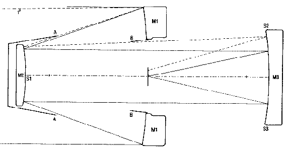
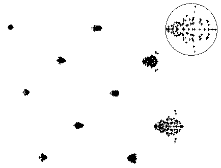
The layout is shown in Fig.1 and the dimensions are given in Table 1, which includes the locations of the sky fog baffles. The optical performance is illustrated by the spot diagrams in Fig. 2 and image spreads and distortion are given in Table 2.
The performance of the curved-field Mersenne-schmidt systems given in Paper 1 was compared there with that of other telescopes (Chretien 1022; Couder 1926; Schmidt 1931; Bowen &Vaughan 1973; Korsch 1977; Robb 1978; Angel, Woolf & Epps 1982; Epps & Takeda 1983; Willstrop 1983). Here the flat-field version will be compared only with the earlier curved-field versions; for other comparisons the reader is referred to Paper 1.
Table 1. Construction details of a F2.6 flat-field Mersenne-schmidt.
|
| Focal length = 12009.6mm. Dimensions are given in millimeters |
|---|
| component | radius* | Distance |
Material | Diameter |
|
| Mirror 1 | -16000 | | | 5000.0 |
| | 4959.57 | air | |
| Mirror 2 | 6080.9818 | | | 2086 |
| | 9888.544 | air | |
| Mirror 3 | -9888.544 | | | 3236 |
| | 4944.1092 | air | |
| Focal surf. | Plane | | | 683 |
|
* Axial radii of mirrors; profiles are given below in term of power series. The
second diameter for the primary mirror refers to the perforation.

Figure 1. Optical arrangement of the F/2.6 flat-field Mersenne-Schmidt. M1, M2 and M3 are the
mirrors; AA and BB are sky fog baffles which allow uniform illumination over aamp; field 2' in diameter, and provide freedome from sky fog over 3%quot; diameter. Continuos lines are from an object at the center of the field and passing through the edge of the aperture; dotted lines show the path of a ray from an object 11º off axis. The chain line is the optical axis, and the marks indicate the location of the mirrors in the curved-field version (Paper 1) with the primary mirror of the same aperture and the focal length. S1, S2 and S3 are the locations of sources and sensors for optical alignment (see text, Section 4.5).

Figure 2. Spot diagrams for the F/2.6 flat-field Mersenne-Schmidt. The images are separated vertically only to avoid overlapping. Angles off-axis in degrees are: top row - 0.0, 0.75 and 1,5. Second row - 0.45, and 1.2. 3rd row - 0.15 and 0.9. $4th row - 0.6 and 1.05. The circle is 0.5 arcsec in diameter.
Table 2. Optical performance of F/2.6 flat-field Mersenne-Schmidt
|
| Angle off axis | Image spreads on plane focal surface | Distortion
correction
term (arcsec) | "Best" image
surface |
| total | rms | unit = 10-6mm | |
|
| 0.00 | 0.0390 | 0.0125 | | 0.04 |
| 0.15 | 0.0474 x 0.0488 | 0.0186 x 0.0142 | -5 | .13 |
| 0.30 | 0.0673 x 0.0602 | 0.0287 x 0.0177 | -1 | .36 |
| 0.45 | 0.0774 x 0.0625 | 0.0364 x 0.0204 | +3 | 0.64 |
| 0.60 | 0.0852 x 0.0523 | 0.0391 x 0.0208 | +16 | 0.81 |
| 0.75 | 0.0890 x 0.0456 | 0.0355 x 0.0196 | +27 | 0.68 |
| 0.90 | 0.0770 x 0.0463 | 0.0284 x 0.0221 | +26 | -0.04 |
| 1.05 | 0.0768 x 0.0863 | 0.0382 x 0.0362 | +4 | -1.73 |
| 1.20 | 0.1417 x 0.0863 | 0.0382 x 0.0627 | -32- | 5.19 |
| 1.35 | 0.2683 x 0.3039 | 0.1417 x 0.0990 | -31 | -11,69 |
| 1.50 | 0.4676 x 0.4352 | 0.2309 x 0.1424 | +8 | -22.73 |
|
| Distortions - The distance of the image from the optical axis, in mm,
is r=227.0603º + 02785 º3 + correction term. The %quot;best%quot' image
surface is that which passes through those images with the least rms
spread, departures from the plane image surface are given in units of
10-3mm. Positive values mean that the best image lies further than
the plane surface from the tertiary mirror. |
|


