From the Monthly Notes of the Royal Astronomical Society (1965) Vol. 216 pp 411-427
3 Comparisons with the curved field Mersenne-Schmidt.
The present design has a flat focal surface, which may be a significant advantage in some applications. The optical performance is approximately a factor of 2 worse than that in Paper 1, but it is still significantly better than the best performance normally allowed by the Earth's atmosphere. The field is limited to 3 º in diameter by the larger image scale and the smaller diameter of the beam of parallel light between the secondary and tertiary mirrors' a larger plateholder would introduce further obstruction of the light.
The tube length is about 24 % greater than in the earlier design, but this might not necessarily lead to a larger, more expensive dome; it is usually necessary to make the dome rather larger than the minimum size required to clear the moving parts of the telescope in order to be able to move the primary mirror to and from the aluminizing plant.
The secondary mirror of the flat-field version is smaller and the central obstruction to the incoming light is less but the smaller secondary mirror would be more difficult to figure because it is a convex ellipsoid, almost a paroboloid of aperture F/1.6 rather than almost spherical.
Distortion amounts to 0.94mm at 341mm (1.5 deg) off axis (see Table 2). In the curved field design it is substantially smaller and is comparable with the distortion caused by bending th photographic plate.
Table 3 Mirror spacings to compensate for a plane filter
|
| Row | Filter |
M1M2 | M2M
3 | M3 Focus | Notes |
| 1 | 0.0mm | 4959.57 | 9888.544 | 4944.109 | Design as in Table 1 |
| 2 | 3.0mm | 4959.57 | 9888.544 |
4942.1516 | Filter ins.; refocused |
| 3 | 3.0mm | 4959.448 | 9888.544 |
4942.4597 | Sph. ab. adjusted refocus |
| 4 | 3.0mm | 4959.448 | 9893.094 |
4942.4595 | Coma also sdj. refocused |
|
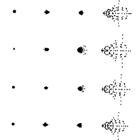
As in the curved field version the use of a plane parallel filter introduces spherical aberration over the whole field and coma off axis but these can be corrected by adjustments to the mirror spacings as shown in Fig.3' the changes in mirror spacing are given in Table 3. The changes in the mirror spacings required to correct the curved field version when a filter is included were given in Paper 1 and the spot diagrams corresponding to Fig.. 3 have been published elsewhere (Willstrop 1984b).
 Figure 3. The effect of inserting a filter 3mm thick. In each row the images are 0.0, 0.0, 1.0 and 1.5 º off axis. Top row, the design as in Table 1, no filter, Second row a filter 3mm thick has been inserted and the telescope refocused to minimize the axial images spread. Third row, the separation of the primary and secondary mirrors has been reduced by 0.122mm to restore the spherical aberration in the axial image as nearly as possible to the same state as in the top row and a further focus correction had been applied. Bottom row the separation of the secondary and tertiary mirrors has been increased by 4.55mm to restore the coma correction as nearly as possible to the same state as in the top row and a very small focus correction has been applied. The spacings are given in Table 3.

