4.1 Construction of the mirrors.
The easiest optical surface to generate (or "figure") accurately is undoubtedly a concave spherical mirror' it can also be null tested at its center of curvature without auxiliary optics. The primary mirrors of the telescopes proposed here and in Paper 1 are close approximations to concave paraboloids of relative aperture F/1.6 and the secondary mirror proposed here approximates a convex ellipsoid (e = 0.8783...; F/1.46) while that in Paper 1 is almost spherical. Small convex mirrors such as the secondary mirror in
the model may be tested by interference against a concave mirror of known figure but this method is impractical in the case of large convex mirrors, especially if they are mad of a translucent material such as Cervit or Zerodur or have a ribbed or honeycomb structure. It is therefore necessary to consider how these mirrors would be made and tested. The tertiary mirror of each telescope is sufficiently close to spherical for well-known techniques to be used.
Large astronomical telescope mirrors are normally polished lying face-up centered on a turntable with an aluminium alloy tool carrying facets of pitch and using a suspension of finely powdered rare earth oxides in water as the polishing agent. The channels between the pitch facets need to be cut clear to the tool in order to allow the pitch to flow slowly and evenly to maintain good contact with the mirror; they also facilitate the distribution of the polishing agent. If the tool is moved laterally across a spherical mirror the pitch facets will remain in good contact; if the mirror is appreciably aspheric and the tool
relatively rigid the contact will not be maintained as the pitch cannot flow sufficiently in a short time. To maintain good contact which is essential for accurate figuring the tool must have considerable flexibility. To minimize the bending required of the tool it is usually moved laterally by not more than a few inches.
The greater part of the polishing action comes from the rotation of the mirror on the turntable while the polishing tool is restrained from rotating. The lateral movements of the tool are required to blend the effect of each facet over the range of radii on the mirror and so minimize "tree ring" effects. Following experience with the F/2.5 mirrors of UKIRT (3.8m aperture) and the 4.2m William Herschel Telescope it is believed that with carful design which would include finite element analysis, an aluminium alloy too could be made flexible enough to polish a F/1.6 paraboloidal mirror of comparable size. Because of the
way the flexibility and the asphericity scale with size, there is more tolerance in the design of a tool for a bigger mirror. On the other hand, if a "pilot model" of, say 1m aperture, were to be built, a more flexible material would be required (D. S. Brown, private communication).
Optical testing is required to guide the modification of the polishing tool from time to time to concentrate its action on those zones of the mirror that are too high. It is most practical to test large paraboloidal mirrors at their mean center of curvature. Some means of compensating the large amount of spherical aberration that results from using the mirror in non-parallel light is then required. This can be achieved with small auxiliary lenses as discussed in Section 4.2. The convex approximately spherical (Paper 1) or ellipsoidal (this paper) secondary mirror requires larger auxiliary optics in order to refocus the light after reflection; arrangements for testing the secondary mirrors are discussed in Section 4.3
4.2 Optical Null Test Arrangements of Concave Primary Mirrors
The Foucault (1859) Knife-edge test is extremely sensitive when it is applied to a spherical mirror as the knife edge is at its center of curvature but the paraboloid tested at its mean center of curvature shows moving shadow edges which must be located accurately as a function of the movement of the knife edge along the axis if reliable results are to be obtained. Couder (1927) is believed to have been the first to use a small negative lens with an appropriate amount of primary (third order) spherical aberration to cancel that of a paraboloid under test, so yielding a null test; if the mirror then appears to darken evenly all over as the knife edge moves across the image, the mirror is correctly figured (to the accuracy of the third-order aberrations). Burch (1936) described the use of spherical mirrors to test a paraboloidal mirror. Dall (1947) described a null test using a small positive lens.
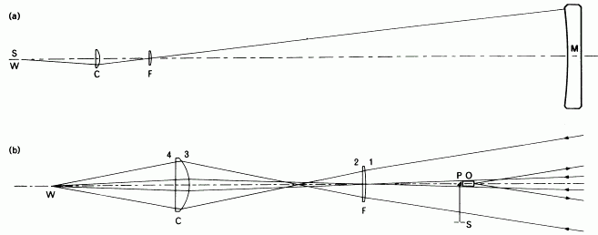
All of these test arrangements are able only to correct third-order spherical aberration or, strictly, to reduce it to the small amount required to balance the uncorrected fifth and higher orders, so they are limited to paraboloids of rather small relative aperture. Burch added a small aspheric mirror in the later stages of refiguring a 35 inch F/3.75 mirror. Offner (1963), faced with the problem of testing 36 inch F/4 paraboloids for the Stratascope experiment, was obliged to find an improved test arrangement and used two plano-convex lenses (Fig. 4a). This arrangement allows both third and fifth-order spherical
aberrations to be reduced to the small quantifies needed to balance the uncorrected seventh and higher orders and it has been used successfully for mirrors as fast as F/2.5. It is not essential for the light to pass through the lenses both before and after the reflection of the mirror and a single passage (Fig. 4b) clearly halves the sensitivity of the test to errors of construction of the lenses or variations of their refractive index but does require larger lenses.
When an Offner compensator is used to test a paraboloid or near-paraboloid of aperture F/1.6 the optical path residuals are found to be unacceptably large. D. S. Brown (private communication) then confidently recommended, on the basis of algebraic analysis he had carried out some time ago and not published, that allowing the field lens to assume a meniscus form would provide another degree of freedom to permit third-, fifth- and seventh-order spherical aberration to be reduced to the small amounts required to balance that of the ninth and higher orders. The writer was able quickly to confirm this using
an optimizing program based on ray-tracing subroutines (Willstrop, unpublished) on the STARLINK VAX 11/780 at Bambridge. This program adjusts the radii of curvature of surfaces 1 and 3 (see Fig. 4b) for given positions and thicknesses of the lenses; an outer loop in the program makes initially small changes in the distance of the field lens from the mirror, and if the rms path differences (rmspds) are reduced after surfaces 1 and 3 have been re-optimized then the field lens is moved in progressively larger steps. When the rmspds increase the best position for the field lens is determined, assuming that the rmspds are a quadratic function of the position of the lenses. If the last three positions of the lenses were widely spaced this is repeated with closer spacing. If the initial data are close to the optimum a solution is
reached in about 5sec. cpu time. It is therefore practical and easy for the user to make several runs changing the starting value of the radius of curvature of the second surface of the field lens. The first time the writer made this change of the rmspds was reduced to one tenth of the smallest value previously obtained; later adjustments made a further improvement by a factor of more than 5.
Subsequently it was noticed that Offner had suggested changing the shape of the compensator lens (which he calls the imaging lens) to reduce the residual path differences; this has since been found to give a reduction by a factor of about 15, compared with two plano-convex lenses in the case of an F/2.5 paraboloid.
Details of the construction of modified Offner compensators are given in Tables 4, 5 and 8 for a true paraboloid without t central perforation for the primary mirror of the curved-field telescope (Paper 1) and that of the flat-field telescope described here. The latter two mirrors have large central perforations and this feature results in smaller rmspds than in the case of the true paraboloid.

| Modified Offner compensator for F/1.6 paraboloid. Glass type BK7. Dimensions are given in millimeters. | |||||
| Source | Radius | Axial distance | Refractive Index | Diameter | |
| 15800.0 | 1.0 | ||||
| Mirror | -16000.0 | 5000.0 $ | |||
| 16237.06 | 1.0 | ||||
| Field Lens | 554.3348 | ||||
| 12.7 | 1.51759 | 113.0 | |||
| 11185.0 | |||||
| 700.0 | 1.0 | ||||
| Compensator | |||||
| 161.9332 | |||||
| 55.0 | 1.51759 | 189.1 | |||
| plane | |||||
| 404.1110 | 1.0 | ||||
| Focus | |||||
| * Axial curvature of paraboloid | |||||
| $ The perforation of the mirror is 1000mm in diameter. | |||||
| R.M.S. Path difference = 2.157x 10⁻⁵ mm. | |||||
| Comments refer to tables 4, 5 and 6. | |||||
| Modified Offner compensator for primary mirror (Paper 1). (Curved field telescope, field 4 º in diameter) Glass type: Schott BK7. Dimensions are given in millimeters. | |||||
| Source | Radius | Axial distance | Refractive Index | Diameter | |
| 15900.0 | 1.0 | ||||
| Mirror | -16000.0 * | 5000.0 $ | |||
| 16158,05 | 1.0 | ||||
| Field lens | 535.5886 | ||||
| 12.7 | 1.51759 | 102.7 | |||
| 5180.0 | |||||
| 700.0 | 1.0 | ||||
| Compensator | 165.9225 | ||||
| 55.0 | 1.51759 | 192.6 | |||
| plane. | |||||
| 513.8870 | 1.0 | ||||
| Focus. | |||||
| Modified Offner compensator for primary mirror (this paper). (Flat-field telescope, field 3 º in diameter). Glass type: Schott BK7. Dimensions are given in millimeters. | |||||
| Source | Radius | Axial distance | Refractive Index | Diameter | |
| 15900.0 | 1.0 | ||||
| Mirror | -16000.0 * | 5000.0 $ | |||
| Field lens | 557.9091 | ||||
| 12.7 | 1.51759 | 100.0 | |||
| 10782.5 | |||||
| Compensator | 166.8262 | ||||
| 55.0 | 1.51759 | 194.6 | |||
| plane | |||||
| 510.4684 | 1.0 | ||||
| Focus | |||||
4.3 Optical Null Test Arrangement For Convex Secondary Mirrors.
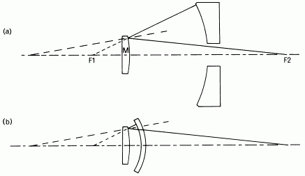
The convex secondary mirrors of most telescope are hyperbolic and are normally tested during manufacture by the Hindle test (Fig. 5). In the original form of the test (Fig. 5a), a large perforated concave spherical mirror was used. A small area around the center of the mirror remains untested in this arrangement. It is now more usually to use a meniscus lens, which need not be much larger than the mirror to be tested (Fig 5b). The whole of the mirror can be tested but the three reflections at the uncoated surfaces call for long exposures. After the reflection in the meniscus lens the light is converging towards one conjugate focus and after the second reflection in the mirror the light is converging towards the other focus. In the case of convex ellipsoidal mirrors the light should be convergent before the first reflection in the mirror and divergent after the second. To achieve this, the meniscus lens would need to be replaced by a lens with positive power. Such a lens with aperture larger than the mirror to be tested and sufficient power to obtain real object and image points would be very thick and would contribute signaficant abberation of its own. A sufficiently large and homogenous piece of optical glass might not be obtainable.
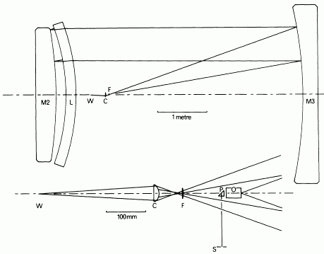
The arrangement shown in Fig.6 is analternative. The meniscus lens is of uniform thickness, and therefore requires less glass than one with substantial positive power. Immediately before and after transmission through the meniscus lens the light is approximately parallel but can be brough to a real image (and come from a real source) by reflection in a concave mirror. The tertiary mirror of the telescope can be used as this focusing mirror, either before or after it has been given the slightly aspheric form required in the telescope. It can be argued that it should be used in this test before being aspherized,
as the surface thne is likely to be smoother, but D. S. Brown (private communication) has remarked that a large mirror would not necessarily ever be spherical; time would be saved by aiming for the aspheric form from the start. It will be evident that the arrangement of the secondary and tertiary mirrors and the path of the light resembles that in the completer telescope (see Fig. 1), except that the primary mirror delivering converging light is replace by the menicus lens. If the meniscus lens were infinitely thing it would controbute no aberrrations of itw own but it needs substantial thickness in order to retain its figure and that the intermediate focus, close to the source, has substantial spherical aberration. This can be
corrected by a modified Offner compensator which delivers a cond of light of more moderate convergance to a wavefront-shearing interferometer or other test instrument. The source can be an image of a slit, formed by a high quality microscope objective designed for use without a cover glass and of a numerical aperture 0.35 or larger for the curved field telescope, 0.25 for the flat-field telescope.
It is believed that this optical test for the secondary mirror, depending on the use of the tertiary mirror, is original. In one respect it is foreshadowed by a null test for the Schmidt telescope correctors which uses the finished spherical mirror (Willstrop 1980). The dimensions of the test arrangement for the nearly spherical convex mirror of the curved-field telescope of Paper 1 are given in Table 7 and those for the ellipsoidal convex mirror of the flat-field telescope in Table 8.

Figure 5. (a) The original Hindle test for convex hyperbolodial mirrors. F1 and F2 are the conjugate foci of the mirror M, the center of curvature of the spherical concave mirror must coincide with F1. This mirror mucst be perforated and a small part of the mirror under test cannot be examined. There are two unsilvered reflections at the mirror.
(b) The modified Hindle test using a menincus elns in place of teh large spherical mirror. The entire surface of the mirrro can be tested but there are now three unsilvered reflections rather long photographic exposures are required.

| New null test for a convex, approximately spherical mirror. (Secondary mirror of curved field telescope; Paper 1.) Glass type:Schott BK7. Dimensions are given in millimeters. | ||||
| Source | Radius | Axial distance | Refractive Index | Diameter |
| 3788.4957 | 1.0 | |||
| Mirror | -8000.0 * | |||
| 4600.0 | 1.0 | |||
| Meniscus lens | 4200.0 | |||
| 200.0 | 1.571759 | |||
| 4000.0 | 2644.0 | |||
| 200.0 | 1.0 | |||
| Mirror | 8000.0 $ | 2699.5 | ||
| 200.0 | 1.0 | |||
| Lens (m) | -4000.0 | 2699.5 | ||
| 200.0 | 1.0 | |||
| Mensiscus | -4000.0 | 2605.9 | ||
| 2000.0 | 1.51759 | |||
| -4200.0 | 2693.0 | |||
| 4500.0 | 1.0 | |||
| Field lens | 60.45168 | |||
| 3.63 | 1.51759 | 25.5 | ||
| 366.5 | ||||
| 56.587 | 1.0 | |||
| Compensator | 28.05124 | |||
| 14.2857 | 1.51759 | 35.0 | ||
| plane | ||||
| 292.1062 | 1.0 | |||
| Focus | ||||
| * Axial curvature of paraboloid | ||||
| $ The perforation of the mirror is 1000mm in diameter. | ||||
| R.M.S. Path difference = 3.4026x 10⁻⁵ mm. on this double-pass test. | ||||
| New null test for a convex approximately ellipsoidal mirror. (Secondary
mirror fo flat-field telescope: this paper.) Glass type: BK7. Dimensions are given in millimeters. | ||||
| Source | Radius | Axial distance | Refractive Index | Diameter |
| 4588,7178 | 1.0 | |||
| Mirror | -988.544 * | |||
| 5200.0 | 1.0 | |||
| Meniscus lens | 3550.0 | |||
| 150.0 | 1.51759 | |||
| 3400.0 | ||||
| 500.0 | 1.0 | |||
| Mirror | 6080.9818 $ | 2100.0 | ||
| 500.0 | 1.0 | |||
| Lens (m) | -3400.0 | 2384.5 | ||
| 500.0 | 1.0 | |||
| Mirror | 6080.9818 $ | 2106.9 | ||
| 500.0 | 1.0 | |||
| Meniscus lens | 3400.0 | 2098.7 | ||
| 150.0 | 1.51759 | |||
| 3550.0 | 2130.1 | |||
| 5200.0 | 1.0 | |||
| Mirror | -988.544 * | 2081.6 | ||
| 4709.5178 $ | 1.0 | |||
| Field Lens | 254.5902 | |||
| 12.7 | 1.51759 | 44.0 | ||
| 2513.1 | ||||
| 220.0 | 1.0 | |||
| Compensator | 85.1030 | |||
| 50.0 | 1.51759 | 82.0 | ||
| plane | ||||
| 870.3091 | 1.0 | |||
| Focus. | ||||
| * Axial curvature of tertiary mirror, defined by power series. | ||||
| $ Axial curvature of secondary mirror under test, defined by power series. See Table 1. | ||||
| R.M.S. Path difference = 9.632x10⁻⁷ mm (in this double-pass test). | ||||