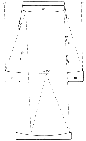
 | Figure 1. Optical arrangement of the Mersenne-Schmidt. The perforated primary mirror, M1 is approximately paraboloid, the convex secondary, M2 and the concave tertiary, M3, are approximately spherical. Dimensions and details of figuring are given in Table 2. On the left of this figure Baffle A is sufficient to shield the central 2º of diameter of the field from stray sky light reflected by the tertiary mirror. To shield the full 4º; diameter this baffle can be extended to B, or A can be used with the conical baffle CD. The obscuration can be reduced by the arrangement shown on the right of the diagram. For an explanation, see the text Section 3.2. The dimensions and locations of the baffles are given in Table 2. |
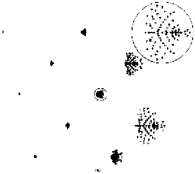
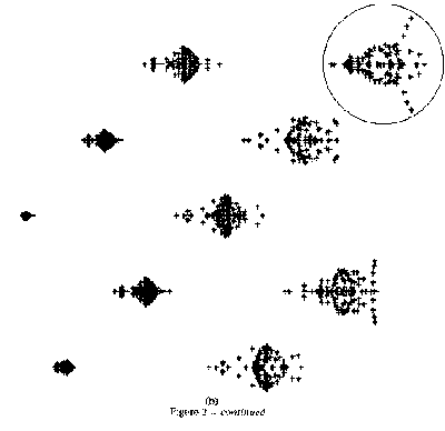
Two sets of spot diagrams, for images on axis and at .2º, .4º ... 2º off axis, are shown in figs 2a and 2b, for two designs which use the same mirror spacings, apertures and axial curvatures, but different asphericities. The first of these gives diffraction-limited images on axis, 0.049 arcsec total (ray theoretical) image spread (0.23 arcsec rms diameter) at 1º off axis and 0.44 arcsec total image spread (0.263 arcsec rms) at 2º, or from the ground over 4º. The second design also has diffraction-limited images on axis, but is adjusted to improve the performance of 2º off axis, at some cost to the image quality at intermediate angles. The maximum image spread is 0.31 arcsec, 0.17 arcsec rms diameter. Details of the performance at intermediate angles are given in Table 2.
| Focal Length 8000mm. Dimensions in mm. | ||||
| Component | Radius | Distance | Material | Diameter |
| Mirror 1 | -16000.0 | 5000.0 (2969.0) | ||
| 4000.0 | air | |||
| Mirror 2 | 8000 | 2643.0 | ||
| 8000.0 | air | |||
| Mirror 3 | -8000.0 | 3530.0 | ||
| 4000.0 | air | |||
| Focal Surface | 8000.0 | 558.5 | ||
| Notes: | ||||
| The second diameter for the primary mirror refers to the perforation. | ||||
| The mirrors of version 1 (images under 0.049 arcsec over 2º field) have profiles given by the power series: | ||||
| x1 = 3.125x10⁻³ r2 -5.8428x10⁻²³ r6 -6.355x10⁻³¹ r8 | ||||
| x2 = 6.25x10⁻⁵ r2 2.44237x10⁻¹³ r4 1.34267x10⁻²⁰ r6 6.136x10⁻²⁸ r8 | ||||
| x3 = 6.25x10⁻⁵ r2 -2.44141x10⁻¹³ r4 -2.20914x10⁻²¹ r6 -2.921x10⁻²⁹ r8 | ||||
| For comparisons with mirrors 2 and 3, the nearest sphere fits the series: | ||||
| xs = 6.25x10⁻⁵ r2 2.4414x10⁻¹³ r4 1.9073x10⁻²¹ r6 1.85x10⁻²⁹ r8 2.1675x10-37 r10 | ||||
| The surface of least rms image spread is: xf - 6.257x10⁻⁵ r2 | ||||
| The mirrors of version 2 (images under 0.31 arcsec over 4º field) have profiles given by the power series: | ||||
| x1 = 3.125x10⁻⁵ r2 -4.04734x10⁻²³ r6 -1.574x10⁻³⁰ r8 | ||||
| x2 = 6.25x10⁻⁵ r2 2.442386x10⁻¹³ r4 1.2168x10⁻²⁰ r6 8.506x10⁻²⁸ r8 | ||||
| x3 - -6.25x10⁻⁵ r2 -2.441405x10⁻¹³ r4 -2.1016x10⁻²¹ r6 -3.657x10⁻²⁹ r8 | ||||
 |  |
| Figure 2. Spot diagrams for images in the Mersenne-Schmidt: (a) Version 1: (b) Version 2 (see Table 1). In each set, the top row shows images on axis and 1º and 2º off axis, the second row .6º and 1.4º off axis. The diameters of the circles are (a) 0.1 and 0.5 arcsec, (b) 0.4 arcsec. | |
| Angle | Version 1 | Version 2 | ||||
| off | Total image | rms diam. | Total image | rms diam. | ||
| Axis | spread arcsec | arcsec | spread arcsec | arcsec | ||
| 0.0 | 0.0030 | 0.0014 | 0.0042 | 0.0026 | ||
| 0.2 | 0.0269 x 0.0055 | 0.0034 | 0.0286 x 0.0181 | 0.0157 | ||
| 0.4 | 0.0131 x 0.0133 | 0.0068 | 0.0623 x 0.0395 | 0.0328 | ||
| 0.6 | 0.0201 x 0.0243 | 0.0113 | 0.1162 x 0.0633 | 0.0528 | ||
| 0.8 | 0.0267 x 0.0366 | 0.0163 | 0.1814 x 0.0866 | 0.0753 | ||
| 1.0 | 0.0265 x 0.0489 | 0.0229 | 0.2518 x 0.1126 | 0.0991 | ||
| 1.2 | 0.0543 x 0.0648 | 0.0346 | 0.2847 x 0.1308 | 0.1201 | ||
| 1.4 | 0.0866 x 0.1114 | 0.0584 | 0.3050 x 0.1443 | 0.1357 | ||
| 1.6 | 0.1388 x 0.1825 | 0.1010 | 0.3072 x 0.1512 | 0.1463 | ||
| 1.8 | 0.2274 x 0.2865 | 0.1675 | 0.2011 x 0.2033 | 0.1539 | ||
| 2.0 | 0.3380 x 0.4381 | 0.2631 | 0.3074 x 0.3070 | 0.1686 | ||
| The first of each pair of number in the columns headed total image spread is measured in the direction of the radius to the center of the field; the second is in the tangential direction. Distortion amounts to less than 10 arcsec at 2º off axis; a simple formula with linear and cubic terms fits the image locations to better than 0.02 arcsec at all angles. | ||||||
It may be of interest to record here the method by which the designs in Table 1 were reached. Initially the mirrors were strictly paraboloidal and spherical. This arrangement is corrected for Seidel spherical aberration, coma and astigmatism, but on axis higher order spherical aberratino leads to images 27.7 arcsec in diameter. This was corrected by making the secondary mirror aspheric, reducing the (ray theoretic) axial image spread to .0002 arcsec. The figuring required was a turned down edge, amounting to about 40um in the r6 term, 3.4um in the r8 and 0.3um in r4. The image 1º off axis still suffered from coma and astigmatism, and was 3.9 arcsec (radially)x 2.1 arcsec. Coma was estimated from four rays in the principal plane, two at the edge of the aperture and two near the center, in the focused image; astigmatism was estimated from the distance along the axis between the image having least rms spread in the radial direction, and that with least tangential spread. These faults con be corrected by more figuring, if one of the mirrors is modified by changing the coefficient of r10 in its description then the axial image can be restored to its previous quality by making a compensating change in the coefficient of r8 in either of the other two mirrors. There are three possible pairs of mirrors that can be figured, each pair changes was estimated from the distance along the axis between the image having least rms spread in the radial direction, and that with least tangential spread. These faults can be corrected by more figuring, if some of the mirrors is modified by changing the coefficient of rn in its description then the axial image can be e restored to its previous quality by making a compensating change in the coefficient of rn in either of the other two mirrors. There are three possible pairs of mirrors that can be figured, each pair changes the coma and astigmatism in different proportions, but only two of these changes are independent. Nevertheless, this is enough to allow both coma and astigmatism, evaluated as described above, to be eliminated. In principle this can be done using the r4, r6 or higher terms in the power series, but a change in the r4 term is equivalent to a change in eccentricities of the mirrors, and the system is already corrected in the Seidel approximations by using a paraboloid and two spheres. It is therefore logical to make the corrections by changes in the r6 terms.
It is notable that the r6 figures used to remove coma that was estimated from rays at the ends and near the center of one diameter of the aperture, and astigmatism, also result in very small residual lateral ray displacements at intermediate points in the aperture. Further investigation showed that if the coma and astigmatism had been removed by applying r8 figuring those residuals would have had roughly the same form, but with their signs reversed, and the residual would have been larger. It was clear that the images could be improved still further by making most of the correction of coma and astigmatism with the r6 terms and a small part by the r8 terms. Trial and error showed that 89% of r6 and 11% of r8 gave something near the best possible correction at all angles off axis up to 2º and reduced the image 1º off axis to 0.052x0.046 arcsec (total spread), 0.0227 arcsec (rms diameter). Rounding off the construction data caused some small changes in the image sizes. Automatic optimization of the optical performance by computer has not been used at any stage, if it were some further improvement of the images 1º off axis would be expected, while the images near the axis would be slightly degraded. A similar method was used to arrive at the second design, except that coma and astigmatism were removed at 2º off axis.
The improvement which these two designs show compared with the Paul and Baker versions results from the use of the same basic principles (confocal paraboloids and Schmidt camera) and the acceptance of small but highly significant departures from the strictly paraboloidal primary and spherical tertiary mirrors used by Baker.
Both of these designs are adjusted for use without a filter. When a filter of thickness t = 3mm and refractive index of n = 1.52 is inserted spherical aberration is introduced over the whole field of view, and coma off axis. The monochromatic image spread on axis is then 12um (0.3 arcsec at the present focal length of 8m). Fortunately the image quality can be restored approximately by changing only the separation of the mirrors. In Version 1 (2º field) the maximum ray-theoretic image spread is reduced to 0.044 arcsec by changing the mirror spacings to 3999.42mm and 8004.83mm; in Version 2 (4º field) spacings of 3999.40 and 8004.50mm result in a maximum spread of 0.323 arcsec, only 5% larger than with no filter. In white light there is also a defocusing effect amounting to t-delta(1/n); in order to keep the additional image spread from this cause under 2um (about 0.05 arcsec at 8m focal length) the range of foci should not exceed 6.4um at F/1.6 (if the focus is correct at the center of the passband). Passbands should then be kept under about 25nm at 390nm, 50nm at 500nm and 100nm at 650nm if the filter is 3mm thick and of a type of glass similar to Schott GG495.
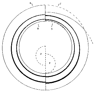
 | Figure 3. Entrance pupils of the Mersenne-Schmidt with baffles as on the right of Fig. 1: at the left, 1º off axis, right, 2º. Along the line AB, the circles represent: the outer edge of the primary mirror; the obstruction in the converging light caused by baffle GH; the same for baffle EF; the shadow of the edge E on the primary mirror. Along CD (2º off axis): the outer edge of the primary mirror (dotted); the edge of the perforation in the primary mirror; the obstruction in the converging light caused by baffle GH; the same for EF; the shadow of baffle K on the primary mirror; the shadow of baffle E (dotted where this is within the shadow of K). A circular plateholder P covering 4º diameter is everywhere within the central shadow, but a square plateholder would cause a small additional loss of light near the edge of the field. |
| Baffle | Function | Radius | Height | Height |
| Outside | Inside | |||
| A | Shields central 2º diameter | 1595 | 1589 | 3235 |
| B | Shields 4º diameter | 1685 | 1679 | 2935 |
| C | With A, shields 4º | 1550 | 1537 | 900 |
| D | 1451 | 1438 | 1400 | |
| E | Together, baffles E-K shield | 1536 | 1523 | 800 |
| F | A field 4º in diameter | 1459 | 1446 | 1200 |
| G | 1407 | 1399 | 2470 | |
| K | 1480 | 1470 | 3650 | |
| Notes. Data are rounded to the nearest mm. The thickness of the baffles is assumed to be 0.5 inch (13mm) except the edges of baffles A, B and K which are 0.25 inch (6mm). Radii are measure form the optical axis of the telescope, and heights above the pol of the primary mirror. For further explanation see the text, Section 3. | ||||