I've had a number of people ask about a quick test for mirrors, especially mirrors in the telescope tube (Newts for one as they are the most common). Remember that this test is done at the ROC which is twice the FL so you can indeed test a scope without having to remove the mirror from the scope, just tilt it down enough so that you can see inside from the ROC point. The secondary, unless it's a really huge one, will not affect the test in any real meaningful way. This article shows a quick diagram of how to build a nice portable Ronchi Tester.
It might be noted before we go any further that when using this tester by hand, the lines exhibited by the Ronchi grating will be fleeting if you actually hand hold the tester as you are usually unable to hold the tester in your hand steady enough to get good results and you should really use something to hold it still, both in range and position. I have successfully seen the images normally seen by most but am unable to hold them for more than a bit of a second or so. With that caveat said, on to the design of the tester.
The original design of the Ronchi Test was with a pinhole source (or a slit if so desired) and the grating only covered the return beam. This original version of the test has the problem of finding the returned beam and is useful only if you have the various parts necessary like a bright light source to set it up. Some optician found out that if you put the light source behind a grating and shone the light through the grating and then read the test through another part of the same grating, you could get the same results. This is the type of tester that this article describes.
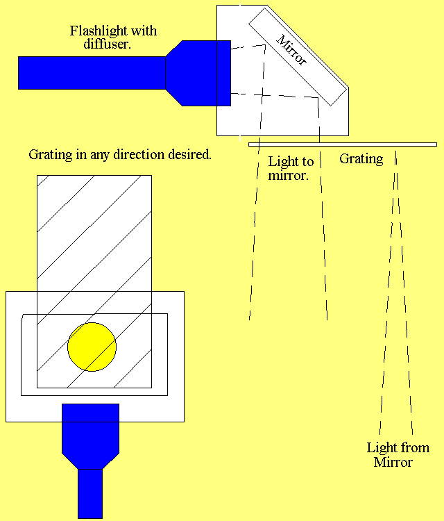
The design of the tester can be seen in the Fig. 1 below where the flashlight is a common MiniMag type that you turn the head to turn it on and off. An easy to find front surface mirror of some size is used for the mirror to turn the beam by 90° so that the flashlight becomes a nice handle. The light then goes out of the housing and goes through the bottom part of the grating.
When the light comes back from the mirror, you set the tester so that it goes through the top part of the grating and then to your eye. You do want your eye close to the grating so that you can see all of the mirror illuminated by the tester at one time.
I've built one from plastic sheet material and have seen another built out of a simple 2"x2" block of wood several inches long. The wood one had two holes drilled out of the block so that a MiniMag light could be pressfitted into one hole and, with a small mirror in the hole glued in at a 45° angle with respect to the flashlight so that the light was reflected out the other drilled hole. A piece of film type Ronchi grating material was simply hot melt glued onto the exit face of the wood with some of it sticking up to look through and that was the entire tester. It was an amazing piece of equipment, especially since it was a professional mirror maker owned it and had shown it to me at RTMC.
I returned home and made the one I now have from the pieces of some 3/8" acrylic sheet that I had laying about. One of the things is that you do want to have the mirror in there as otherwise you will have trouble getting your eye close enough to the grating when making a test. It would be interesting if somebody made one as a set of eyeglasses (there is a set of safety glasses out there with "headlights" on them which could be used) and see if that would work well for testing. With such a setup, you could use two small pieces of grating, making sure that you have them aligned the same angle.
After working with the tester for a few days, I made a cover for the grating so it wouldn't get damaged by storing it about. Next things to do on the list for the tester is a regular stand so that I can set it up so others can see what the results of the Ronchi test are without the tester moving about.
One of the things that you may want to do is to replace the MiniMag with a LED light source (making sure to try and get it to a diffused light) and that should work as well. I have used the tester without the diffusion and the problem that happens is that the intensity of the returned beam varys a fair bit as you move about. You will quickly find that this becomes distracting so the diffusion element in the light source will be desired. I did the diffusion with some KimWipes (a brand of wipes that are fairly openweave), using 4 layers (first try) to get the diffusion.
The Ronchi test is an interesting test for the surface of a mirror. For spherical surfaces tested at the ROC of the surface, the test produces straight lines which can easily be measured with the appropriate measurement tools to find out how straight the surface is. The test produces results that show that things are right or not right. Unfortunately, it takes a bit of math (which I have no plans on getting into) to figure out what the actual results are in a quantitative way. However, the qualitative results do indicate whether or not the surface's shape is good or not. Things like zonal errors, especially the turned edge are quite visible in the images.
When you look at the typical parabolic mirror, you can, again with some math, figure the shape of the mirror form the shape of the lines on the mirror after you have measured them - something that can be a bit difficult. However, the zones will show up as steps in the position of the lines and the thing to remember here is that the lines are further apart as the ROC at that position gets closer to the grating. In other words, if you look at a mirror and the center of the mirror has the lines twice as wide as the edge, the edge's ROC is twice as close as the center's is and you have the grating inside the ROC. Also, if the edges hook the same way as the curvature of the lines, the edge is turned down and if they hook in the opposite direction as the general curvature of the lines, the edge is turned up.
Next is that if you make a holder for a piece of grating, you can put the holder in your telescope focuser (no EyePiece is used in this test!) in place of the EP, then you can test using a point source (a star) at infinite distance and the grating at the focus and thus, see if the whole telescope system is good at one time.
The image of a star's light coming in should be a large disk of light with the image of the secondary in the center of the image (just like when you look down the tube when there's no EP in the scope) and there will be lines from the grating in the image which show the shape of the wavefront and it's errors. As you rack the grating in and out, you will see the number of lines grow and shrink. As the star passes by the grating (you aren't tracking quite right) you will also see the lines pass over the image of the mirror.
The next thing that you will see in the image is general crawling of the image about and that crawling is from "seeing" conditions, both tube currents and the external modifications of the light path by the atmosphere that are commonly called "seeing".
A fair number of people have made, or at least tried to make, Ronchi gratings on their printers. This can be done for the coarser gratings with no real problem. However the production of gratings often fails because the persons making the grating miss out on some of the things that happens with making lines on a printer. Remember that 100lpi is a nice size for most of the work that is desired for the hobby. This means that there is one clear and one black line set for every .010" of distance and means that you have to have a resolution of at the least .001" to even begin to be able to produce a decent grating and the line edges need to be straight as possible. This is difficult to do until you really start talking about the 1200dpi printers that have only recently come out. Ragged edges of the grating will produce soft ragged lines on the surface under test which move about as you move the grating about and that will make seeing the true shape of the surface a lot more difficult to see.
The first problem that happens when trying to make the lines is that the most common computer/printer system is the PC Windows system with some printer (often a PostScript type printer) attached to it. The second system is the Mac and a PostScript printer. Both of these systems have a real problem when trying to make accurate drawings with. The picture on the computer screen is only an approximation of the size of the finished product. Second is that there is a number of conversions that happen from this image to the actual dots of black on the transparency film coming out of the printer. What's worse is that the conversions from things like the dimensions of type (measured in points - 1/72" of all of the strange sizes) and the 300dpi or 600dpi of the natural printer resolution tends to make for a skip a line of a dots on occasion as you draw a bunch of lines next to each other across the film. These skips make the grating unusable unless you get enough lines that don't have the skip so that you can cut at the lines where the skip happens. What gets worse is that when you attempt to adjust the spacing of the lines, the calculations tend to have problems which relate to the various conversions that are happening. Another problem is that at 300dpi, you can't specify the dimension correctly at all points as you have to make the lines in sets of 3 dots at the minimum otherwise you have irrational numbers (.333... isn't a number which will produce a dot at the correct place naturally) and as a result, you do lose some ability to make the gratings. The newer 600dpi and 1200dep printers make the ability to make finer lines but you still have the same problems with the 3 problem. If you really want to have a grating direct from the printer, you will need to handle the output directly and that can be fun with PostScript printers as they are not an easy beastie to send info to. HPGL is a bit better but that isn't used as much as it used to be and mostly only for the HP line of printers.
An alternative to directly printing the grating is to print a large format grating and use a camera to photograph it with high resolution/contrast film. This will get rid of the problem of dot resolution with the fine lines and you can even use a plotter type machine to print out the image to be photographed. The problem that happens here is that you have the added expense of an odd film that needs to be processed.
Another thing is to use a Gerber type photoplotter to print out a grating. These machines work by drawing with light on a film and can produce some quite large images but run into the problem of being able to make really fine lines. The machines usually make their lines several hundredths of an inch at the minimum which means that you are only going to be able to do relatively coarse gratings directly. Photoreduction of a pattern made by a Gerber plotter can do a very nice job of making a fine grating.
If you want anything beyond about 300dpi, you will really need to consider something other than even a photoreduction as the grain size becomes a nasty problem at these kinds of sizes. Professional gratings are usually evaporated onto a piece of glass when you get to the smaller sizes and that becomes a bit expensive.
One of the things that you have to remember when doing all of this is that you can get a professionally made 100lpi grating from Edmund Scientific in a 2" square piece of glass for about $30 each plus shipping. A 1" square one is, of course, a fair bit cheaper than the larger one. There are other sources of film type gratings for lesser prices than the glass.
There are no hard and fast rules on how to physically build the tester other than the light should shine through the grating that you also look through to see the returned beam - the same piece of grating only because you then have the same angle of the grating lines in both the source and the destination gratings. If you desire to use two pieces of grating, you can do so as long as the grating is about the same LPI and is set at the same angle as the source. I haven't tried two sperate gratings (no need to in this case) and don't know if there is a requirement for them to be the same in LPI so you will be on your own in this regard.
If you have any problems or questions, feel free to ask as the worst that I will do is not answer you if the question is already answered in the article above.