Notes on making Schmidt corrector plates and vacuum pans.
For some reason, there is a dearth of information on making Schmidt corrector plates on the web. This article, I hope, will correct a fair bit of that lack.
When Bernard Schmidt first started working out how to make a plate to correct for the differences between a parabolic surface and a spherical surface for his Schmidt camera, he came to the understanding that a piece of glass under stress would assume the catenary shape, a shape that is very close to that of the paraboloid shape. The rest of the story is history.
The whole process of making a vacuum pan and polishing out a Schmidt corrector plate is fairly easy to do and is described below.
 The basic shape of the pan is shown at the right with a step in it so that you can place the glass with a little ledge to center it up in the pan. The lefthand part of the pan shows the hole that also needs to be put into the pan when you are done with the turning. I did a 1/4" pipe thread at the end of the hole to accept the various parts of the valve and vacuum gauge. There isn't much in the way of parts that you need for making a vacuum pan. You need a vacuum gauge of some kind, preferably one with a 270 degree face on it, a 1/4 turn ball valve to hold the vacuum yet allow for the drawing of that vacuum, some pipe pieces to put that onto the pan itself, and a piece of aluminum big enough to be able to take the diameter of the corrector plate that you are going to make. Try not to make the aluminum too thin as you will be building up a fair vacuum on the pan (('m running 12.5 inches of vacuum on my pan).
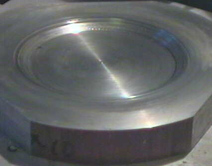 The first thing that needs to be made is a vacuum pan so that the glass may be stressed into the right shape. This is best done on a lathe with a piece of aluminum or steel large enough to take the full diameter of the glass plate. Mount up the piece of metal and turn the face of it so that it is all decently flat. Next is to dig into the center area with a hole that the glass will sink into. A tenth of an inch is usually about enough but you may go deeper if you so desire. I'll note that after you make one corrector plate, you may wish to do another smaller one on occasion so you might want to put some additional steps in as you go, hoping that the sizes are the right ones for each size corrector that you end up doing. Make sure that the last cut is the facing cut on the metal so that the glass has a smooth surface to lay on. A sharp tool and a gentle cut will insure that the face is flat. The photo at the right shows the vacuum pan that I did.
Below are more pictures of the details of the vacuum pan.
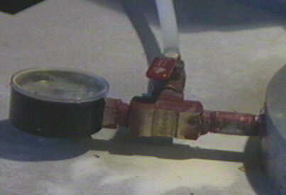 | The plumbing of the gauge and valve. The red stuff is some paint used to insure that the plumbing is indeed sealed. |
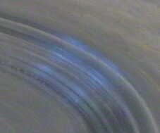 | Closer detail of the steps in the aluminum forming the pan. The first step is to locate the glass on the pan. The second step has a rounded bottom which tends to show as a number of small steps due to the lathe cutter stopping at various points inside the edge. |
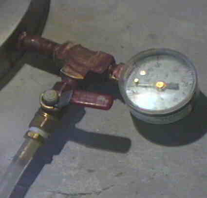 | Detail of the plumbing from the other side. The clearish white plastic on the bottom is tubing to draw the vacuum. |
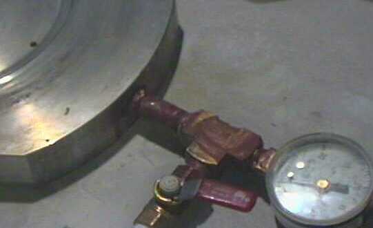 | | Showing the plumbing to the hole in the pan center area.
After you have made the pan, the next thing is to use it. The first uses of vacuum pans used air in the pan to work on the glass. I've found that instad of air, you may wish to use water as I have done. Air is rather compressible and thus it takes a bit of flow to get any changes in the vacuum. This may be nice but one thing it doesn't do is indicate where there may be a leak in the seal around the glass. The first side of the glass that I did I used some silicone grease as the seal and this would last for a while before failing with the grease being dragged into the pan. On the second side, I used some bathtub caulking as it doesn't flow. This stuff is a bit harder to get the glass off of the pan but it will come off. With the grease, you just gently blew into the pan and the glass popped up, allowing you to lift the glass off. The caulk took a bit more pressure but it also comes free.
When I did both sides of the corrector I eventually used water in the pan and this ended up being a lot easier to maintain the vacuum as the valve also has a minor leak and the water flows slower than the air does. I just filled the pan with water and placed the glass on top and sealed it to the aluminum without regard for the water in the seal area. I'll note that locations where the seal failed were not necessarily the places where water escaped as the sealing happened.
Before you actually start drawing a vacuum, it is wise to find out how much vacuum that you need to actually have in order to get the correct shape. Dave Rowe has an Excel spreadsheet that will do this very nicely on his webpage. Either that or you can do the calculations by hand and find the vacuum needed to do the job.
After you have drawn the vacuum and gotten rid of any leaks, you can then start the process of finishing up the corrector plate from the flat surface that you got on the glass. You should make a tool from dental stone to do the final grinding on both sides (if you need to spread the correction on both sides as I have done with the F1.95 primary that I am applying the corrector to) and then polish the glass up with polishing pads (see my mirrormaking article for more info on polishing pads) applied. You may be able to get away with not having to grind the glass to a better shape if you are doing something more gentle for a focal ratio than what I have done but just polish. With pads, you can actually polish the surface starting with 12 micron grit as the polishing agent! This will make the polish happen a lot faster than with CeO and you can go eventually to CeO after the glass shows being polished up. With my corrector, the polish quickly came up in the near edge zone with the polish expanding from theere in both directions, hitting the edge about the time the polish hit the 50% area of the glass. Eventually, the center is polished out and this is the time to switch to a pitch lap to finish the glass up to a fine polish.
When you get both sides polished out, it is time to test the glass and the easy thing is to just put in front of a spherical surface and see if the shape is smooth without a turned edge of any significance - don't forget that the edge can be turned down as you are going to be mounting the glass by its edge which will hide any minimal TDE from the optical path.
On a more critical test, the double pass Foucault test where the light comes from the source, hits the primary, the corrector plate to a flat and back again to the KE where a null test is should happen. Any failures of the null test are either in the primary or in the corrector plate and you need to figure out which is the problem.
Good luck with making a corrector plate! If you have any questions, feel free to ask them as this is how I can catch missing parts and clarify muddy parts of my articles.