1 - Basic Formulas for a Cassegrain Telescope.
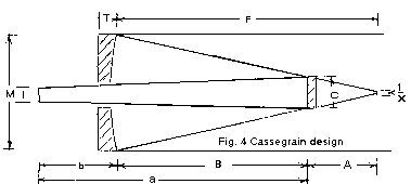
The important basic dimensions of a Cassegrain telescope are:
- M - the diameter of the primary mirror
- C - The diameter of the secondary mirror
- F - the focal length of the primary
- B - the separation between the primary and the secondary
- b - the distance between the primary mirror and the focal plane
- A - the distance between the secondary to the focal point of the primary
- a - the distance between the system focal plane and the secondary
Other terms that need to be defined for future use:
- m - magnification of the system
- R2 - Radius of Curvature of the secondary
- Ft - Effective focal length if the system
- C - Diameter of the secondary to illuminate the center of the focal plane. Note that the secondary will be larger than this to fully illuminate the entire focal plane.
- Kp - Conic Constant of the primary mirror
- Ks - Conic Constant of the secondary mirror
- d directly in front of a value (da for example) is the differential movement of the value, i.e. a change of a from 1.4 inches to 1.5 inches is a da of 0.1 inches.
The purpose of a Cassegrain secondary mirror is to slow the convergence of the light cone from the primary by increasing the system focal length, direct it to the focal plane and correct as best possible the aberrations in the image caused by the primary. Because the secondary is convex, it has a "magnification factor" that is referred to as m. This factor tells how much the secondary mirror magnifies the focal length of the primary by. The overall focal length of the instrument is designated as Ft.
With that introduction, here are the important equations for designing the dimensions of a Cassegrain telescope. They can be manipulated as needed to solve for various quantities. Most of these equations are from Texereau, another is from another source. The surface shapes for the surfaces will be described in the next section.
- Ft = F * m System focal length
- m = a / A "Magnification" of system
- A = (F + b) / (m + 1) secondary mirror to focal plane distance
- R2 = 2 * A * m / (m - 1) Radius of curvature of the secondary mirror
- R2 = (2 * A * a) /(A - a) Another way of finding the ROC of the secondary
- C = M * A / F Diameter of secondary required to fully illuminate the center of the field.
- s = a / B Defined for convenience for later formulas
Next is a handy equation (and a transformation of it) for calculating the radius of curvature of the secondary if you know the values of A and a. This is formula is needed if you already have a primary that you wish to use in a Cassegrain. After you choose a magnification, you know A and a, and all you need is the secondary's radius of curvature, R2. Below that is a manipulated version of the equation to solve for a that is given by Richard Buchroeder from page 135 of the original version of
"Advanced Telescope Making Techniques, Vol. 1". Please note that WillBell is now producing an updated version of the book set (3 volumes) which is organized by subject rather than by date. The original set is only available on the used book market and I'd suggest that in either case that you buy all three volumes as they all contain interesting info.. The first equation is solved for R2 and the second equation is the same relationship solved for a
- R2 = 2 / ((1 / A) - (1 / a)
- a = (R2 * A) / (R2 - 2 * A)
The second equation is important because a determines where the focal plane will be. If we have a in terms of both A and R2, we realize that we can find the sensitivity of the focal plane position as a function of the location of the secondary and the radius of curvature (R2) of the secondary. This means we can figure out how much moving the secondary moves the focal plane, and how much an error in the secondary's curvature (caused by grinding in a curve that's slightly off) will affect the focal plane position. To get these quantities, we simply take the derivative of the second equation with respect to A and R2. Those formulae are given below.
- da / dA = R22 / (4 * A2 - 4 * A * R2 / R22)
- da / dR2 = p(R2 - 2 * A) - R2 * A / (R2 - 2 * A)2
The first number means that for every unit of length (say a millimeter) that the secondary is moved towards the primary mirror, the focal plane moves da / dA farther behind the primary. This derivative (rate of change) is only valid for the position of the secondary, and it will change if the secondary is moved. The A value should be recalculated if large moves are anticipated)
The second number means that an error of plus (or minus) one millimeter in R2 moves the focal planeda / dR2mm farther from the secondary mirror with a negative number meaning that the distance is closer.
Now, you might wonder why the focal plane moves so much more than we expect. Common sense seems to indicate that, for the 12.5" F/12.5 Cass, with an F/4.2 primary and a secondary magnification of 12.5/4.2 = 3, moving the secondary 0.01" toward the primary should move the focal plane back 0.01" * 3 = 0.03". But this is NOT true. Instead, it moves 0.0886" back. So where does the extra sensitivity come from? Well, when you decrease the spacing between the secondary and primary, the focal length of the system actually gets longer, and this adds dramatically to the sensitivity to spacing changes. This is why adjusting the spacing between an aspheric secondary and the primary changes the system correction.
The sensitivity to changes in these quantities increases as the magnification rises. For an example, a 14.25" F/21 Cassegrain is:
- da / dA = 31.2, da / dR2 = -10.51
As we can see, both quantities rise quite significantly. So, that planetary Cassegrain you're thinking about building is going to require you to design the tube correctly so you don't have a of secondary travel to put the focal plane exactly where you want it. Be aware that the change in length of the tube structure due to temperature will cause focus shift over the course of a night because that causes the distance between the primary and secondary mirrors to decrease.
2 - Mirror Prescription/Design Formulas.
These are the formulas used to calculate the "prescriptions" of the primary and secondary mirrors for three types of Cassegrain telescopes - the Dall-Kirkham, classical and Ritchey-Chretien. The prescription is the form of the aspheric shape of the mirror. First, realize that in the various Cass designs, the mirrors require various amounts of aspherization to work correctly.
Here is a page that describes the different ways of defining this asphereic shape, eccentricity, Conic Constant and so forth.
Now, you don't really need this next formula, but some of the more math-oriented ATMs might enjoy seeing it. It was also obtained from ATM Vol 1, A general formula for the shape of a cross section of a mirror's surface is given as a reference by:
- z =(y2 / R) / (1 + (1 - (1 + K) (y / R)2)1/2)
The optical axis lies along the z-axis, and the y-axis is the transverse axis, so z represents the mirror's height as a function of y, the distance from the optical axis. The center of the mirror is at y = 0, and its edge is at y = mirror radius. R is the radius of curvature of the mirror. The variable K is the conic constant range for the mirror surface of interest.
;
- For a sphere, K= 0 (Dall-Kirkham secondary)
- For an ellipse, 0 > K > -1 (Dall-Kirkham primary)
- For a parabola, K = -1 (Newtonian and classical Cassegrain primary)
- For a hyperbola, K < -1 ; (Ritchey-Chretien primary and secondary, classical Cassegrain secondary)
Basically, the parameter K determines the type of shape a concave or convex mirror has. If K > 0, we have an oblate spheroid, basically a shape with a shorter radius as you go out in distance from the center rather than a longer distance in the outer zones that you'd have with a hyperboloid, ellipsiod or parabola. In order to design a Cassegrain, we need to calculate it according to the type of Cassegrain we wish to make. Thankfully, the formulas are already worked out in Richard Buchroeder's article mentioned above - he has provided a convenient table, and I have merely substituted the variable names I have been previously used here.
| Type of the Cassegrain |
Kp for primary mirror
Conic Constant of Primary | Ks for secondary mirror Conic Constant for Secondary |
| Dall-Kirkham |
| s (m -1)(m+1)2 | | | __________ | - 1 |
| m3 (m + s) | |
| 0 (sphere) |
| Classical Cassegrain | -1 (parabola) | | -4m | | | _________ | - 1 |
| (m-1)2 | |
| or - ((a + A) / (a - A))2 |
|
| Ritchey-Chretien |
| | -4m(m-1)
- 2(m+s) | |
| ___________________ | - 1 |
| (m-1)3 | |
|
Table 1:
Equations to determine the conic constant of primary and secondary mirrors in Cassegrain telescopes
So how to figure the mirrors? Calculate K values for the mirrors in your Cassegrain. For example, in a 12.5" F/12.5 Classical Cassegrain, Kp = -1 for the primary and Ks = -4.00 for the secondary. The primary is a parabola, so we know how to test that. Since Ks = -4.00 for the secondary, for example, it is a hyperbola with 4.00 times the correction of a parabola, so if we are to make a concave test plate, we simply multiply all the ideal knife edge displacements by 4.00 to get the proper shape of the secondary.. It's that simple!
Test plates are simply the curve in the concave form so you can test the surface with the regular ol' Foucault test without any difficulty. When you get that done, you can then start on the actual secondary itself.. Do the ROC on the secondary as needed and don't forget to polish up the back surface (no particular shape is needed, just a clear surface) so you can do interference fringe testing with the test plate which you have already completed.. You want to make the two surfaces (the test plate to the secondary) match so that you get nice straight interference lines between the two surfaces, just like you'd be getting with the comparison of two flats together. A program like FringeXP will do a nice job of telling you where and how far off you are in the shape between the two surfaces.
Let's say we designed a R-C and it has a primary, Kp = -1.04167. This means that for Foucault testing, we simply multiply the ideal Foucault knife edge positions for a parabola by 1.04167, and that gives us the ideal knife edge positions for the hyperbolic primary mirror (or concave test plate for the secondary mirror with the appropriate multiplier to the parabola values). . Many are surprised to find out that the primary mirror for an R-C is only 1.04167 times more corrected than a parabola. The things that make an R-C difficult are the typically fast focal ratio of the primary that is often used to gain a relatively fast telescope and the significant correction that must be applied to the secondary mirror as a result.
3 - Other Cassegrain Tips.
a) Correction issues for Cassegrains with hyperboloidal secondary mirrors (classical, R-C):
The correction of a Cassegrain optical system with an aspheric secondary mirror (classical, R-C) is dependent on the primary-secondary distance. This is because the secondary's conic constant, Ks is a function of how far it is from the primary mirror and the distance to the focal plane. This is why it is difficult to match a secondary mirror that is already finished to a primary mirror - the chances of the secondary having the right value of Ks are small.. the secondary has the right conic constant and it is placed at the proper design location, the system will be perfectly corrected for spherical aberration. However, if you see spherical aberration, digest the following:
- -If the secondary mirror is moved AWAY from the primary mirror, the correction of the system will INCREASE.
- -If the secondary is moved TOWARD the primary mirror, the correction of the system will DECREASE. (This assumes it is large enough to be moved and still intercept all of the light from the primary).
- -If you are figuring a Cassegrain secondary using star testing, increasing the correction of the secondary will decrease the correction of the system.
So, if you see a bit of overcorrection in your classical or R-C, move the secondary mirror closer to the primary and deal with the focus shift, or figure the secondary to have a bit more correction. Why is this true? Think about it this way - if we move the secondary farther from the primary, we use only a smaller, central portion of the secondary. In effect, the hyperbola in the center of the secondary has less correction than that of the full mirror, and this causes the light in the outer zones of the mirror to converge slightly more slowly, which is the same as increasing the correction of the whole system. So, the effect on a Cassegrain system of changing the correction of the secondary mirror is the OPPOSITE of changing the correction of the primary mirror.
b) Correction issues for Dall-Kirkham:
For Dall-Kirkham, the position of the (spherical) secondary makes a difference, too, as evidenced by the presence of the variables s and m in the equation for the value of Kp for the primary mirror. Those two variables are dependent on a, B an A, which vary with the location of the secondary mirror. A quick numerical calculation using the mirror spacings for my 12.5" classical Cassegrain indicate that if it were a Dall-Kirkham, then moving the secondary toward the primary would require a slightly less corrected primary. So, moving the secondary toward the primary should slightly increase the correction of a Dall-Kirkham system in the system. This is the opposite of what happens in the other Cassegrains with hyperboloidal secondaries. This system is less sensitive to movement of the secondary than a classical or R-C.
c) Size of illuminated field:
In order for an area of the focal plane to be "fully illuminated", it must get light from all of the primary and secondary mirrors. For a Cassegrain this means that the secondary mirror must be large enough to allow the entire primary mirror to be "seen" from the parts of the focal plane that we wish to fully illuminate. For example, if we know the location of the focal plane and we put our eye there at its center, we should see the reflection of the primary mirror centered in the secondary mirror. If only the very center of the field is fully illuminated (say the central 0.05"), then we should see the reflection of the edge of the primary mirror right at the edge of the secondary mirror. If the fully illuminated field is larger, say 0.5" in diameter, then we should be able to move our eye off the optical axis by 0.25" from the center of the field and still see the entire primary mirror in the secondary mirror, though it will no longer be centered in the secondary
Here's a thread on the ATM list that discusses testing a convex hyperbolic secondary through the glass. Needless to say, you do need to use optical glass for doing this test. There are even some files for OSLO-LT (usable in the EDU version as the EDU version is an upgrade and it reads files from earlier versions) that show examples of finding the necessary Conic Constants and other such necessary specifications for the secondary.
Now that we've been through the formulas, let's actually design a telescope. The telescope to be designed has a primary of 9 inches and has a focal length of 60 inches and it is going to be a R-C design. The light will be coming out one of the pivots for the Dec. axis so the focal plane will be about 5.5 inches outside of the side of the tube. The scope will be using 2 inch eyepieces so the focal plane needs to be 2" in diameter. Here's the basics to start with:
- Primary diameter = 9 inches
- Primary focal length = 30 inches
- Eyepiece diameter = 2 inches
- Effective focal length = 90 inches.
- Tube diameter = 11 inches
- Distance of the focal plane 3 inches from the edge of the tube
- No hole in the primary
First is to figure out where the focal plane is relative to the centerline of the telescope:
FPoffset = Tube diameter/2 + outside length = 11/2 +3 = 8.5 inches
Next is to figure out where the tertiary mirror should be and that is subject to personal choice and a distance of 2 inches in front of the primary is a good idea as the mirror will be slightly larger in diameter than 2 inches. We'll subtract that 2 inches from the distance between the tertiary mirror and the focal plane to determine the distance b so we end up with 6.5 inches for the distance.
With a magnification of 3 and the effective focal length of 90 inches which will make it an F10 system. Thus, the distance A ends up being:
A = (F + b) / (m + 1) = (30 + 6.5) / (3 + 1) = 36.5 / 4 = 9.125
Thus the secondary is going to be 9.125 inches behind the focal point of the primary or 20.875 inches from the primary. This makes the distance from the system focal plane 20.875 - 2 = 18.875 inches where the tertiary mirror is and since the total distance of a is going to be 3 times that 9.125 inches (27.375 inches), that means that the focal plane will be 20.875 inches minus 27.375 inches or 8.5 inches from the centerline of the scope.
Next is to figure out what the ROC of the secondary is and that is the formula:
R 2 = 2 * A * m / (m - 1) = 2 * 9.125 * 3 / 3-1 = 54.75 / 2 = 27.375 inches
Next we want to find the diameter of the secondary which is the formula:
C = M * A / F = 9 * 9.125 / 30 =82.125 / 30 = 2.74 inches
So 2.75 inches will be quite close enough and add in about another 0.25 inches for mounting on the outside of the mirror makes the secondary to be 3 inches in diameter for a working size. This also allows for a little bit of room for any turned edge which can be covered by the mounting.
This completes the major dimensions of the Cassegrain telescope. All that is left is to determine the shape of the primary and secondary mirrors. This is done with the two formulas below. The first is the shape of the primary which is:
s = a / B = 27.375 / 20.875 = 1.31
Kp = -2 * s / m3 -1 = -2.62 / 27 - 1= -0.09 -1 = -1.09
This means that the primary is going to be 9 percent stronger than a parabola so multiply the values for a parabola in the Foucault test to get the right numbers for the primary.
Next is to derive the shape for the secondary. This formula is a bit more lengthy and is:
Ks = -4 (m (m - 1) - 2 (m + 1) / (m-1)3 -1 = -4 (3 (2) / 23 1 = -24 / 8 -1 = 3 - 1 = -4
Thus the secondary is going to be 4 times as strong as a parabola. Doing a test plate with this as the shape will allow the secondary to be tested by fringe testing. The test plate will want to be at least 2.75 inches in diameter and larger if you wish to avoid the TDE or TUE that often happens so a 4 inch diameter test plate with that shape on it will be a nice size. You only need to test the central 2.75 inches of the test plate, preferably more, tho for a good shape.
You should be able to now calculate the necessary dimensions for your Cassegrain telescope from the above example.
I hope I got all of the calculations right. If not, a note to me on the ATM list will fix that problem when I get it.